JF-1A Conductivity Sensor
A440-009
Page 10 of 56
FEBRUARY 2009
instrumentation loop. The supply should have high isolation (>500 Mohm), and
be single point grounded. The current loop should be wired using shielded
twisted pair wire. The shield should also be single point grounded to a solid
earth ground.
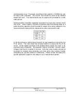
Sensing resistors should be capacitive by-passed to ensure low common mode
loop noise. Sense resistors should be by-passed using the following table as a
guide. Note the capacitor should be rated to sustain the working voltage for the
loop and should comply with the requirements of the local electric code.
R-Loop
By-Pass
OHMS
uF
250
1
350
2.2
500
3.3
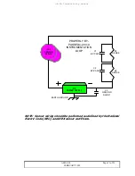
In the figure below a typical loop wiring with by-pass capacitors is shown for the
JF-1A sensor. The loop shows two sensing resistors in series with the JF-1A
sensor. At the negative terminal of the Isolated Power Supply the “loop” is AC
grounded using a capacitor. This capacitor helps to eliminate “common mode”
voltages that may be coupled to the loop. Note the sense resistors should be
connected to isolated input detectors such that entire loop remains floating
eliminating any ground conflicts of differences. Please consult the factory for
specific application support in the design of your measurement system.


