

JF-1A Conductivity Sensor
A440-009
Page 9 of 56
FEBRUARY 2009
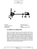
6.3 SENSOR ADAPTOR
The D-2-supplied sensor adaptor should be mounted directly into the outboard
side of the ball valve using Teflon tape or other suitable thread sealer.
6.5 High Flow Rate Installation
See Installation and Safe Use Manual for detailed mechanical installation in high
flow rate lines.
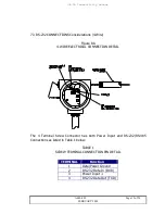
7.0 ELECTRICAL INSTALLATION
See Installation and Safe Use Manual for detailed electrical installation
instructions.
7.1 2-Wire 4-20mA LOOP CONSIDERATIONS
Warning 2-Wire Loop Maximum Resistance including wire can not
exceed 500 ohms, or internal intrinsic over voltage safety devices in
the JF-1A sensor may be activated.
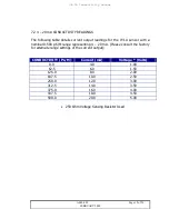
The 4-20 mA Loop supply open circuit voltage must be consistent with the
“Open Circuit Supply” needs of the JF-1A at both its minimum and maximum
indicating currents. The JF-1A has both input voltage limiting protection and
polarity protection. These protection devices affect user supply voltage
requirements. If proper loop supply voltage is not maintained, errors in
indicated conductivity current may occur. The 4-20 mA loop supply voltage
should comply with specifications section of the manual.
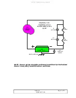
The maximum loop power supply voltage, under all conditions, must also
prevent the voltage across the sensor loop terminals from exceeding the
maximum voltage listed in the specifications section of the manual. If this
condition is not maintained, errors in the current output may occur.
D-2 recommends that a 24 VDC isolated supply be used to power the


