Step
Action
2
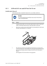
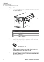
Remove the two rubber protective caps from the optical fiber receptacles on
the right side of the housing.
1
2
3
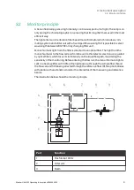
Part
Function
1
Protective cap
2
Rubber sleeve
3
Black shrinking tube
3
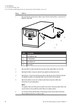
Connect the two optical fibers to the housing by carefully inserting them
into the sockets and tightening the nuts fingertight using the fiber detach-
ment tool supplied. Do not overtighten.
(Fiber detachment tool)
Note:
The optical fiber end with black shrinking tubing shall be connected to the
rear socket connector on the side of Monitor UVis-920.
4
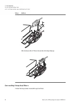
Slide the rubber sleeves on the two optical fibers onto the connectors. Make
sure that the sleeves are pushed tight to the housing to prevent dust, fluid or
light entering the connection.
4 Installation
4.5 Installing the flow cells
4.5.1 UV Flow Cell 2 mm and UV Flow Cell 10 mm
34
Monitor UVis-920 Operating Instructions 29055049 AF

