PSoC Analog Coprocessor Pioneer Kit Guide, Doc. # 002-11190 Rev. *B
33
Kit Operation
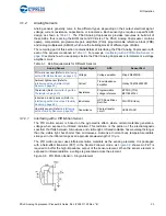
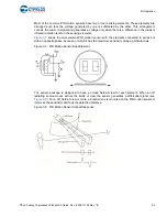
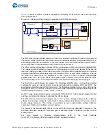
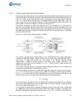
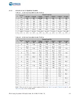
Tables to identify the 0
resistors connected to each of the sensors and the headers are also
provided on the bottom side of the PSoC Analog Coprocessor Pioneer board, as shown in
Figure 3-16. Sensor and Header Pin Connections
P3[4] Inductive proximity sensor
Output of LPF
R126
J2.5
R125
P0[2] Inductive proximity sensor
Series resistor of Inductive
sensor
R128
J6.1
R129
P1[5] Humidity sensor
Connector J17
N/A (J17)
J4.3
R155
P1[7] Humidity sensor
Reference capacitor
R133
J3.2
R10
Table 3-3. List of 0
Resistors Connecting PSoC Pins to Sensors and Headers
(continued)
Pin
Sensor
Where on Sensor Circuit
0
for
sensor
Header
0
for
header

