PSoC Analog Coprocessor Pioneer Kit Guide, Doc. # 002-11190 Rev. *B
20
Kit Operation
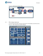
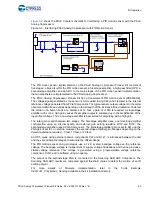
Figure 3-4. Block Diagram of Power supply
3.1.1
PSoC Analog Coprocessor
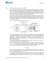
The PSoC Analog Coprocessor device has an extensive set of analog features and other resources.
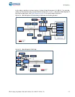
Figure 3-5. PSoC Analog Coprocessor Block Diagram
Voltage
Regulator
(Cypress
PMIC)
Power
LED
VIN
(terminal
block)
OR
‐
ing
Diodes
VDD
Source
Selection
(switch)
VBUS
VBUS
Shield
(5V)
6~12V
Regulator
control
(ON/OFF)
Shield
(5V)
3V
Coin
cell
Arduino
Compatible
Power
Header
(to
baseboard)
Arduino
Compatible
Power
Header
(to
shield)
3.3V
1.8/3.3V/5V
3.3V
5V
Reset
VIN
VDD
Voltage
Selection
(jumper)
VDD
Resettable
Fuse
Regulator
ON/OFF
control
Power
Signal
Programm
a
b
le Interconne
ct and
Routi
n
g
GPIO/
Smart
I/O x8
PSoC
®
Analog Coprocessor
SCB x3
TCPWM x8
12-bit SAR
Universal Analog Block
CMP
x2
I/O Subsystem
Programmable Analog Blocks
GPIO
x8
GPIO
x6
Opamp
x4
GPIO
x8
GPIO
x8
WCO
Cortex
®
-M0+
48 MHz
Analog
Filter
12-bit
VDAC
14-bit
Delta-
Sigma
CapSense
7-bit
IDAC
7-bit
IDAC
AMUX
x38
Signal Processing Engine
Flash
(16KB to 32KB)
SRAM
(2KB to 4KB)
DMA
10-bit
Single-slope
ADC
PRB


