PSoC Analog Coprocessor Pioneer Kit Guide, Doc. # 002-11190 Rev. *B
44
A.3
Using the FM24V10 F-RAM
This section describes advanced features of the PSoC Analog Coprocessor Pioneer Kit as well as
the corresponding projects. It can be used as a reference to use these features for other applica-
tions, according to the needs of the project.
The PSoC Analog Coprocessor Pioneer board has an onboard ferroelectric RAM chip that can hold
up to 1 Mb of data. The chip provides an I2C communication interface for data access. It is hard-
wired to the I2C interface (P4[0] and P4[1] of the PSoC Analog Coprocessor); the same lines are
routed to the PSoC 5LP I2C interface. Because the F-RAM device is an I2C slave, it can be
accessed or shared among various I2C masters on the same lines. For more details on the F-RAM
device, refer to the device
A.3.1
Address Selection
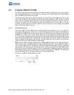
The slave address of the F-RAM device consists of three parts, as shown in
: slave ID,
device select, and page select. Slave ID is an F-RAM family-specific ID provided in the datasheet of
the particular F-RAM device. For the device used on the PSoC Analog Coprocessor Pioneer board
(FM24V10-G), the slave ID is 1010b. Device select bits are set using the two physical pins A2 and
A1 in the device. The setting of these two pins in PSoC Analog Coprocessor Pioneer board is con-
trolled by resistors R44/R39 (A1) and R36/R37 (A2). Because the memory location in the F-RAM
device is divided into two pages of 64 KB each, the page select bit is used to refer to one of the two
pages in which read or write operations will take place.
Note:
The 8-pin SOIC footprint provided for the F-RAM FM24V10 device on the PSoC Analog Pro-
cessor Pioneer Kit is compatible with all I2C-based F-RAM devices from Cypress (FM24Vxx, FM24-
CLxx, and CY15BxxxJ parts). F-RAM parts with more than 64 KB size support only four addresses
(four devices of the same type on the same I2C bus); resistors connected to A1 (R44/R39) and A2
(R36/ R37) pins can be used to select any of the four addresses. F-RAM parts with less than 64 KB
and FM24CLxx parts support eight addresses; resistors connected to A0 (R46/R47), A1 (R44/R39),
and A2 (R36/R37) pins can be used to select one of the eight addresses.
Figure A-5. F-RAM I2C Address Byte Structure

