Software Development
FM0+ S6E1C-Series Starter Kit Guide, Doc. # 002-10542 Rev. *C
43
4. Run the program.
5. The RGB LED (LED4) will blink with green color.
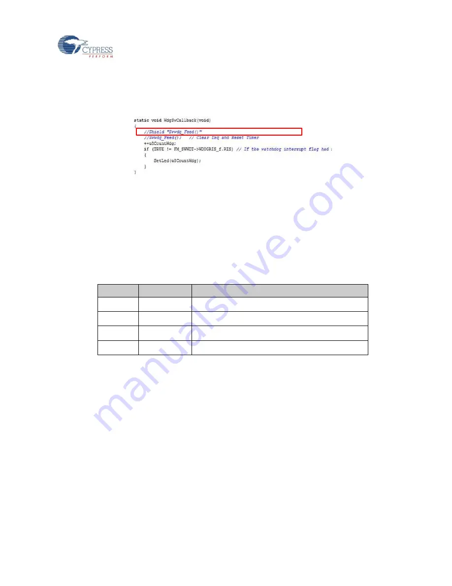
6. Stop the program, comment out the line
Swwdg_Feed();
in main.c file and click
File
->
Save
.
7. Exit from debug mode, then repeat the step 3~4.
8. The RGB LED (LED4) will glow with green color.
4.3 Flash Programming
4.3.1 Programming the S6E1C3 Using FLASH USB DIRECT Programmer
1. FLASH USB DIRECT Programmer gets installed on your PC as part the Kit installer.
2. Make sure the jumpers on the FM0+ S6E1C-Series Starter board are placed according to
the below table.
Table 4-4: Programming Jumper Settings using FLASH USB DRIECT Programmer
Jumper
Position
Description
J1
Open
Sets MB9AF312K (CMSIS-DAP) in run mode.
J2
Closed
Sets S6E1C3 in programming mode
J3
Pin 2 to Pin 3
Sets USB programming mode
J4
Pin 2 to Pin 3
Power from USB port of the S6E1C3 (CN4)
3. Connect the USB cable to CN4 port.
4. Observe that the Power LED (LED3) is glowing green.
5. Launch the FLASH USB DIRECT Programmer from Windows
Start Menu
->
All Programs
>
Cypress
>
FLASH USB DIRECT Programmer
>
USBDirect
6. Select
Target MCU
as
S6E1C32B/C/D
.
7. Select the Motorola S-record file or Intel-HEX format file to be programmed to FLASH
memory in the MCU.
Note:
The HEX file selected in this example is the Test Demo firmware. It is available in
directory
<User_Directory>:\FM0+ S6E1C-Series Starter Kit_Ver01\Firmware
\Demo Projects\Test_Demo_Code
Содержание FM0+ S6E1C-Series
Страница 48: ...FM0 S6E1C Series Starter Kit Guide Doc 002 10542 Rev C 48 A Appendix A 1 Schematic Figure A 1 MCU...
Страница 49: ...Appendix FM0 S6E1C Series Starter Kit Guide Doc 002 10542 Rev C 49 Figure A 2 CMSIS DAP USB...
Страница 50: ...Appendix FM0 S6E1C Series Starter Kit Guide Doc 002 10542 Rev C 50 Figure A 3 Stereo Codec...
Страница 51: ...Appendix FM0 S6E1C Series Starter Kit Guide Doc 002 10542 Rev C 51 Figure A 4 Interfaces...


