


7
DV160 Installation - English
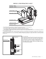
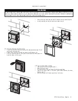
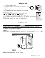
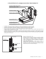
DESIGN AND OPERATING LOGIC
Front panel - NV05
Supply fan - NV01S
Control unit - NV06
Extract fan - NV01E
Heat exchanger - NV04
Supply filter - NV03S
Extracr Filter - NV03E
• The unit casing is made of painted steel, internally filled with a layer of heat- and sound-insulating material.
• The unit casing incorporates a plate heat exchanger, a supply and an extract fan.
• The front panel is installed on the rotating sleeves to enable quick access for the unit servicing.
• The casing bottom is equipped with a protecting service panel to enable service access to the automation unit.
• The G4 supply filter is installed between the fan and the heat exchanger to provide supply of filtered air to the room. The G4 extract filter is installed in
the upper part of the front panel.
• The temperature sensor downstream of the heat exchanger in the exhaust air duct provides the heat exchanger freezing protection. If the exhaust air
temperature drops down below +3 ºC (+37.4 ºF) the heat exchanger freezing danger is registered. In this case the supply fan is turned off and the unit
operates in the extract mode only. After the heat exchanger is warmed up and the freezing danger is no longer imminent the unit reverts to the standard
operation mode.
Intake air
Exhaust air
Extract air
Supply air
Unit operation logic.
Warm stale extract air from the room flows through the air ducts to the unit,
is purified in the extract filter, then it is moved to the heat exchanger and
exhausted outside by the extract fan. Clean cold air from outside is moved
by supply fans to the unit where it is purified through the supply filter. Then
clean air flows through the heat exchanger and is supplied to the room.
Heat energy contained in the warm extract air is transferred to the fresh
intake inside of the heat exchanger. Heat recovery minimizes heat energy
losses and operating heating costs
Содержание DV160
Страница 2: ...2 DV160 Installation English...
Страница 17: ...2 Installation d une DV160 Fran ais...