Curtis Dyna-Fog TWISTER XL 3 3950 Скачать руководство пользователя страница 43

43 


CURTIS 

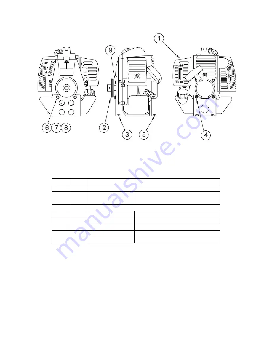
DYNA-FOG® Twister™ XL 3 

TANAKA PF-4000 ENGINE ASSEMBLY P/N 39656-1 

ITEM


QTY.


PART NUMBER


ITEM DESCRIPTION


1  

1  

39656 

ENGINE, 40 CC, TANAKA  

2  

1  

39712 

PULLEY/SHAFT ADAPTER AY  

3  

1  

39658 

BRACKET, L.H.  

4  

12  

120391 

FLAT WASHER, #10  

5  

11  

39659 

BRACKET, R.H.  

6  

39720 

BOLT 6 MM – 1 MM  

7  

2  

120392 

FLAT WASHER, 1/4 

8  

2  

121753 

LOCK WASHER, 1/4  

9  

39710 

WASHER, LOCK, SPLIT, 10 MM  

Содержание TWISTER XL 3 3950

Страница 1: ...3 MODEL 3950 SERIES 4 MOTORIZED KNAPSACK ULV SPRAYER 17335 U S Highway 31 North Westfield Indiana U S A www dynafog com Instruction Manual For Installation Operation and Maintenance Manufactured by Curtis Dyna Fog Ltd ...

Страница 2: ...uffler 23 Engine Fins 23 Blower Assembly 24 Inspection of the Blower 24 25 Air Filter Assembly 26 Removal and Cleaning 26 Poly V Belt and Sheave Drive 27 28 Belt Alignment 27 28 Belt Tension 29 Flushing the System 30 Preventive Maintenance Schedule 31 32 Flow Rate Verification 33 Trouble Shooting Guide 34 35 Exploded Machine Diagram and Parts List 36 37 Straps 38 Engine Blower Plate Assembly 39 40...

Страница 3: ... by which man attempts to control the size of insect populations Due to environmental and economical reasons it is desirable to treat a given area with the least amount of insecticide that can be made effective The most efficient method is to break up the liquids into aerosols and distribute these fine droplets over the target area The small droplets stay suspended for longer periods of time due t...

Страница 4: ...ge steel shaft with two ball bearings Flow Control Interchangeable restricting orifice to produce different flow rates from 1 5 oz min 45 ml min to 17 oz min 500 ml min Nozzle Single high output Microtec nozzle Optional extra twin nozzle kit for higher output Tanks Corrosion resistant high density Polyethylene Formulation 1 U S Gallons 3 78 liters Gasoline 33 3 oz 1 Lt Frame High Strength Aluminum...

Страница 5: ...5 Twister XL 3 Main Components Diagram ...

Страница 6: ...er The engine has a lever type throttle control that allows both idle and working engine operating speeds The blower supplies air thru a flexible hose to the nozzle where the air creates suction on the formulation supply tube The suction in the formulation supply tube causes liquid to be drawn from the formulation tank thru a restricting orifice into a shutoff valve and to the nozzle The nozzles h...

Страница 7: ...L INFORMATION CAUTIONS AND WARNINGS ON THE FORMULATION LABEL WHICH MAY AFFECT PERSONAL SAFETY KNOW ANY DANGERS OF THE SOLUTION USED AND KNOW WHAT TO DO IN CASE OF AN ACCIDENT INVOLVING THE SOLUTION ALWAYS USE THE APPROPRIATE SAFETY EQUIPMENT AND DRESS ACCORDING TO THE CHEMICAL FORMULATION WHICH IS BEING USED WARNING DO NOT USE ANY SUBSTANCES FROM UNMARKED CONTAINERS OR FROM CONTAINERS WITH OBVIOUS...

Страница 8: ...ine includes the appropriate flow control orifice for the viscosity and recommended flow rate of the formulation intended to dispense in accordance with the manufactures label requirements 9 Verify that the belt is in the right position on the sheave 10 Verify the sight position of straps and belts on the frame before use the machine 11 Verify that all safety equipment is in place and is in proper...

Страница 9: ... switch engine kill switch to ON Run position bottom right 3 Depress priming bulb several times to purge air in the carburetor until the flows trough return pipe bottom left diagram 4 Pull choke lever upward to choke position closed bottom center diagram 5 Pull recoil starter briskly taking care to keep the handle in your grasp and not allowing it to snap back 6 When you hear the engine want to st...

Страница 10: ...ration manual before attempting to operate machine 1 Set throttle lever to idle speed bottom right diagram 2 Set ignition switch engine kill switch to ON Run position bottom right 3 Depress priming bulb several times to purge air in the carburetor until the flows trough return pipe bottom left diagram 4 Pull choke lever upward to choke position closed bottom center diagram 5 Pull recoil starter br...

Страница 11: ...ON position turn it close OFF position 2 Return the throttle control lever to the idle speed down position 3 Move the engine kill switch to the stop down position OPERATOR SAFETY Keep all loose items i e Clothing hair jewelry etc away from all moving parts Many of the formulations which can be dispensed with this machine are highly toxic and require special safety equipment Read and observe the fo...

Страница 12: ...valve in close OFF position stopping the flow of formulation Flow rate can be changed by partially opening the valve to the desired position Flow rates shown in Table 1 are based on the ON OFF valve in the maximum open position IMPORTANT To prevent dripping from the nozzle turn the spray valve to close OFF before turning power off The Spray ON OFF valve will provide many hours of service With the ...

Страница 13: ...trol orifice 3 The viscosity of the liquid Various liquids have different viscosities Viscosity is defined as a fluids resistance to flow commonly measured in units of centipoises CP Generally the thicker the liquid the greater the viscosity and the higher the CP number Examples of some liquid viscosities are LIQUID VISCOSITY CP Water 1 Dibrom 3 4 Dow MFC 3 4 Pyrethrin Resmethrin 6 7 Dursban 1 5 U...

Страница 14: ...zle located at the level of the machine base The Dyna Fog Microtec Nozzle will produce 90 of the droplets below 20 microns ULV when used at the recommended flow rates This meets the requirements of all current chemical labels for controlling flying insects When the high flow rate is discharged through a single nozzle the Twister XL will produce larger droplets of 50 microns suitable for applying a...

Страница 15: ...d screw in the adjuster screw check the speed with a tach meter after 5 or 7 minutes of operation readjust if required Reinstall the plastic air cleaner cover Air Filter The air filter must be cleaned periodically from dust and dirt in order to avoid Carburetor malfunctions Starting problems Engine power reductions Unnecessary wear on the engine parts and or abnormal fuel consumption Clean the air...

Страница 16: ... Remove the oil filler cap dipstick and wipe it clean 2 Insert and remove the oil filler cap dipstick without screwing it into the oil filler neck then remove it to check the oil level shown on the dipstick 3 If the oil level is near or below the lower limit mark on the dipstick fill to the bottom edge of the oil fill hole with the oil To avoid overfilling or under filling be sure the engine is in...

Страница 17: ...st you take used oil in a sealed container to your local recycling center or service station for reclamation Do not throw it in the trash pour it on the ground or down a drain 4 Drain the used oil when the engine is warm Warm oil drains quickly and completely Some oil will remain in the engine after draining When refilling with fresh oil start with less than 2 7 oz 80 cm Slowly add enough oil to f...

Страница 18: ...o not pull the recoil starter handle when the top cover is removed You may be injured from the rotating parts or burned by the muffler 2 Disconnect the spark plug cap and remove any dirt from around the spark plug area 3 Remove the spark plug with a 5 8 inch spark plug wrench 4 Inspect the spark plug Replace it if damaged or badly fouled if the sealing washer is in poor condition or if the electro...

Страница 19: ...seats to compress the washer CAUTION A loose spark plug can overheat and damage the engine Overtightening the spark plug can damage the threads in the cylinder head 10 Attach the spark plug cap to the spark plug 11 Install the top cover and tighten the 5 mm hex bolt securely with a hexagon wrench Engine Fins Inspection 1 Loosen the 5 mm hex bolt then remove the top cover 2 Disconnect the spark plu...

Страница 20: ...uel filler neck 3 Pull the fuel filter out through the fuel filler neck by hooking the black fuel tube with a piece of wire such as a partly straightened paper clip 4 Inspect the fuel filter If the fuel filter is dirty wash it gently with nonflammable or high flashpoint solvent If the fuel filter is excessively dirty replace it 5 Remove water and dirt from in the fuel tank by rinsing the inside of...

Страница 21: ... spark arrester and exhaust filter from the muffler Exhaust Filter Cleaning Inspection Pinch the exhaust filter strike lightly with a finger and remove carbon deposits Be careful not to strike strongly The exhaust filter must be free of breaks and holes If it is damaged or fouled excessively have it serviced by your Honda dealer Spark Arrester Cleaning Inspection 1 Use a brush to remove carbon dep...

Страница 22: ... remove the plastic air cleaner cover from the engine loosen the jam nut from the perforated adjuster screw to increase the speed unscrew the adjuster screw to decrease the speed screw in the adjuster screw check the speed with a tach meter after 5 or 7 minutes of operation readjust if required Reinstall the plastic air cleaner cover Air Filter The air filter must be cleaned periodically from dust...

Страница 23: ...k the electrode gap Readjust if required The correct gap is 024 6 mm The spark plug should be replaced after about 100 hours of operation or early if the electrodes are badly eroded NOTE In some areas local laws require using a resistor spark plug to suppress ignition signals If this machine was originally equipped with resistor spark plug use the same type of spark plug for replacement Muffler Re...

Страница 24: ...parate working air from bearing housing BLOWER ASSEMBLY SHOWING CROSS SECTION Inspection of the Blower The Blower should be checked periodically testing the bearings for abnormal conditions or excessive wear checking the rotating fans and other components for corrosion etc To know if detailed inspection of the blower is required a preliminary inspection is required To perform a preliminary inspect...

Страница 25: ...Y INSPECTION OF THE BLOWER After inspection if the Blower Assembly looks in good condition reassemble the belt tighten the blower bolts and apply tension to the belt as indicated at the Belt Transmission section reinstall the Guard Assembly and the Heat Shield Assembly The Blower Assembly is a very critical component which works at high speed about 20 000 RPM then we recommend that the detailed in...

Страница 26: ... the Inlet Filter assembly as this would cause serious damage to the blower unit or personal injury Removal and Cleaning If cleaning procedure is required for the inlet filter loosen and remove the three nylock nuts washers bolts that hold the filter assembly to the thermoset fan end bracket Clean the stainless screen in an approved solvent dry with compressed air or shake to remove excess solvent...

Страница 27: ...follow the instructions indicated in this section BELT ALIGMENT If the engine was removed from the machine for maintenance purposes use a metal strip or similar of 95 24 mm wide as spacer to reinstall the engine in the appropriated place Be sure the surface of the big pulley of the engine makes flat contact with the spacer and the other edge of the spacer makes full contact with the vertical wall ...

Страница 28: ...LD FOUR BOLTS FOR BLOWER HOLDING BELT ADJUSTMENT BRACKET R H 23 mm BELT P N 39504 CHANNEL ENGINE BELT SHEAVE TRANSMISSION BLOWER BELT ALIGMENT If the engine was removed from the machine for maintenance purposes use a metal strip or similar of 90 24 mm wide as spacer to reinstall the engine in the appropriated place Be sure the surface of the big pulley of the engine makes flat contact with the spa...

Страница 29: ... produce non desirable effects as shorter life of bearings engine and blower power reduction higher temperature etc Do not install a new belt on worn sheaves Such sheaves should be replaced to insure a proper fit of the belt in the grooves and prevent slippage and premature belt wear If sheave s change is required they are sold already assembled with the shaft for the blower or on the shaft adapte...

Страница 30: ...on will return into the tank by siphon After about one 1 minute close the shut off valve OFF position 2 Start the engine and allow the machine to run at the working speed 3 Disconnect the formulation line right after the flow control orifice as indicated on the diagram and introduce the end of the hose in about 300 milliliters of flushing solution 4 Open the Fog valve shut off valve to position ON...

Страница 31: ...Rotary Blower Check Air Filter Preliminary Inspection Belt Transmission Check Belt and Pulleys Adjust Belt Tension New Belt Check Pulleys Others Flush Liquid System Check Harness Check Frame Guards Check Flow Control Orifice The intervals shown represent an approximate time period to perform the preventive maintenance Depending on the actual operating environmental conditions it may be necessary t...

Страница 32: ...ry Blower Check Air Filter Preliminary Inspection Belt Transmission Check Belt and Pulleys Adjust Belt Tension New Belt Check Pulleys Others Flush Liquid System Check Harness Check Frame Guards Check Flow Control Orifice The intervals shown represent an approximate time period to perform the preventive maintenance Depending on the actual operating environmental conditions it may be necessary to pe...

Страница 33: ... stop pouring liquid and close the valve Check the remaining amount of liquid in the calibrated container for example 50 ml the difference between the initial and the final volume is the flow rate in ml min 160 ml min for our example 6 Stop the engine and reinstall orifice in place Notes Smaller flow rates requires longer sample time for example three minutes for orifice 19 and the difference betw...

Страница 34: ... dirty or out of internal adjustment a Fuel without 2 cycles oil Tanaka b Exhaust restricted c Spark arrestor clogged d Dirty cooling fins a Check recoil starter Service it if required b Check belt and pulleys for obstructions c Check the engine for rotation Consult the nearest service center d Inspect blower for rotation Consult the nearest service center a Place switch in ON or RUN position b Re...

Страница 35: ...ormulation Filter Clogged d Flow control orifice clogged e Formulation filter above formulation level a Adjust choke b Service air cleaner c Clean adjust or replace d Clean or replace muffler e Clean or replace f check obstructions after blower outlet like bent air hose or obstructed nozzle air outlet a Check alignment and tension Replace if required b Consult nearest service center c Consult near...

Страница 36: ...36 ...

Страница 37: ...00 1 HANDLE AY 19 62313 1 NOZZLE AY 20 39672 1 HOSE AY 21 39616 39656 1 1 ENGINE AY HONDA ENGINE AY TANAKA 22 39651 1 BLOWER AY 23 62369 1 SWITCH ON OFF 24 39657 2 WIRE AY KILL SWITCH 25 132080 4 SCREW 10 24x2 FLSL 26 39674 1 CHANNEL AY TWISTER XL 27 39723 1 GUARD AY BELT 28 85363 4 EXPANSION NUT 29 39699 1 CONTROL AY THROTTLE TWISTER XL 30 39725 1 FUNNEL PLASTIC 31 39596 1 BEAKER PLASTIC 100ML 32...

Страница 38: ...38 STRAPS FOR TWISTER XL 3 MODEL 3950 ITEM QTY P N DESCRIPTION 1 1 39728 HANDLE TWISTER XL 2 1 39765 1 SHOULDER STRAP W HOOK 3 1 39759 HARNESS PAD AY 4 1 39765 SHOULDER STRAP W O HOOK ...

Страница 39: ...39 PLATE AY ENGINE BLOWER P N 39668 ...

Страница 40: ... 1 63921 BRACKET SUPPORT 8 1 30024 RING LOCKING 9 1 62369 SWITCH ON OFF SLIDE TERMINAL 10 1 39657 2 WIRE AY KILL SWITCH 11 1 39657 4 WIRE AY KILL SWITCH HONDA 12 2 39596 BRACKET ISOLATORS SUPPORT 13 4 63148 MOUNT SHOCK 1 4 20 14 8 9419454 NUT NYLOCK 1 4 20 15 2 39711 STIFFENER ENGINE MOUNTING 16 1 39674 CHANNEL AY TWISTER XL 17 18 120392 WASHER FLAT 1 4 REG 18 1 39504 BELT POLY V 16 0 19 1 39616 3...

Страница 41: ...AN SHELL 6 3 B39651 5 FAN ROTATING 7 1 B39651 8 FAN STATIONARY 8 2 B39651 6 SPACER 9 1 B39651 7 FAN STATIONARY 10 1 A39651 4 SPACER 11 2 A159982 SCREW 10 24X2 25 PAN H 12 7 A120391 WASHER FLAT 10 REG 13 1 B39651 31 BRACKET FAN END MACHINED 14 5 A190254 NUT 10 24 LOCK HEX 15 1 10100 18 WASHER NEOPRENE 16 1 C39698 SHAFT BEARING HOUSING AY 17 2 AC39651 14 WASHER 1 5 OD CURTIS DYNA FOG Twister XL 3 ...

Страница 42: ...ULLEY AY HONDA GX 35 3 4 39720 BOLT 6 MM 1 00 MM HEX 4 4 121753 WASHER LOCK 1 4 EXTO 5 4 120392 WASHER FLAT 1 4 REG 6 1 39597 1 WASHER PULLEY AY GX 35 7 2 39612 SPACER ENGINE HONDA GX 35 8 2 120391 WASHER FLAT 10 REGULAR 9 2 120217 WASHER LOCK 10 SPLIT 10 2 39615 BOLT M5 10 MM HEX 11 1 39611 ENGINE CRADLE WELDED AY 12 1 65229 2 SCREW 4 40 X 2 5 PHCR SST ...

Страница 43: ...QTY PART NUMBER ITEM DESCRIPTION 1 1 39656 ENGINE 40 CC TANAKA 2 1 39712 PULLEY SHAFT ADAPTER AY 3 1 39658 BRACKET L H 4 12 120391 FLAT WASHER 10 5 11 39659 BRACKET R H 6 2 39720 BOLT 6 MM 1 MM 7 2 120392 FLAT WASHER 1 4 8 2 121753 LOCK WASHER 1 4 9 1 39710 WASHER LOCK SPLIT 10 MM ...

Страница 44: ... ASSEMBLY 2 1 20054 2 CLAMP 1 5 DIA 3 1 62200 HANDLE 4 1 59962 1 FOAM GRIP 5 1 11719 D RING 6 1 449623 SCREW 10 24 X 7 1 39672 HOSE ASSEMBLY 8 1 39703 1 VALVE BRACKET S S 9 2 39767 FITTING BRASS STRAIGHT 1 4 MPT 10 1 22273 VALVE 11 1 ASC 35 ELBOW BRASS 1 4 MP 1 4 FP 12 1 80296 3 CLAMP GRAY ...

Страница 45: ... 312 GRES 3 1 80447 48 TUBING VINYL 312 GRES 4 1 21158 CLAMP 3 8 PLASTIC 5 1 62584 29 TUBING 1 4 OD POLY 6 1 20054 8 CLAMP HOSE WORM DRIVE NOZZLE ADAPTOR AY P N 39726 ITEM QTY PART NUMBER ITEM DESCRIPTION 1 1 62313 NOZZLE ASSEMBLY 2 1 62495 GASKET 31 THK 3 1 63503 29 ADAPTOR 4 1 62163 8 32 X 375 TYPE F STAPPING SCREW ...

Страница 46: ...the formulation cap If the cap has an outside diameter of 3 0 your Twister XL 3 unit came with P N 39791 formulation tank FORMULATION TANK AY P N 39791 FORMULATION TANK AY P N 39755 ITEM QTY P N DESCRIPTION 1 1 39755 3 TANK 1 GALLON 2 1 39755 1 TANK CAP VENTED ITEM QTY P N DESCRIPTION 1 1 39791 3 TANK 1 GALLON 2 1 39791 1 TANK CAP VENTED ...

Страница 47: ...IPTION 1 1 39680 BRACKET THROTTLE CONTROL 2 1 120361 NUT 10 24 3 1 39729 STOP 4 1 397679 CONTROL THROTTLE TWISTER XL 5 2 58707 NUT 10 24 J TYPE 6 3 157684 SCREW 10 24 X 1 2 TRCR 7 3 120391 WASHER FLAT 10 REG 8 3 138479 WASHER LOCK 10 EXT 9 1 62325 INDICATOR PLATE 10 1 62369 SWITCH ON OFF SL TER 11 6 63414 11 HARNESS WRAP 12 2 39657 WIRE ASSEMBLY KILL SWITCH ...

Страница 48: ...48 ...

Страница 49: ...49 TANAKA PF 4000 ENGINE ONLY ...

Страница 50: ...50 TWISTER XL 3 DUAL NOZZLE ATTACHMENT P N 39716 ...

Страница 51: ...54 2 CLAMP WORM DRIVE 1 5 16 1 63414 4 HARNESS WRAP 17 4 62582 1 NUT 250 PLASTIC GRIP 18 2 62553 1 CONNECTOR UNION 1 4T 19 1 39717 T FRAME AY CLEAR ANODIZE 20 3 58284 FOOT RUBBER 21 2 39529 19 BRACKET NOZZLE 22 2 39567 LABEL SPRAY ON OFF 23 2 39560 VALVE SHUT OFF BARB 24 2 63240 3 BRACKET SHUT OFF VALVE 25 3 159929 SCREW 10 24X5 8 PNCR 26 8 120391 WASHER FLAT 10 REG 27 8 138479 WASHER LOCK 10 EXTO...

Страница 52: ...52 OPTIONAL ...

Страница 53: ... A A A A B A A A A B C D A B DB D E C B A 38 53 ...

Страница 54: ... F 3954 ...

Страница 55: ... F A A B A A A B B C D D E C G H I E J F I K E F K A G L M E EM J A E I A A A A A A A A A B B A N O A N O A 40 55 ...

Страница 56: ... F A A A A A C D A A A B A B A A B C D A B D E C A A A B D A A A A A A A AA A A A C D A A A D E C A A A D E C A B D E C A A A B A A A A A A B B A A A A I L C C PP 41 56 ...

Страница 57: ... F 42 57 ...

Страница 58: ... F A A A A A AA A A A A A A A A A A A A B A A A B A A A A B B B A B D E C A A A A A A A N O A NB O A A A A A A C D A D E C A A A A A A D E C B D E C 43 58 ...

Страница 59: ... F A A A A B 44 59 ...

Страница 60: ... F I E J F B Q A B B R E J D A Q N I JI E E IIHO B Q K A A R R R R R R A R R R R R R B A A 45 60 ...

Страница 61: ...s with 1 3 gallon tanks available in 115 and 230 VAC COMBUSTION ENGINE DRIVEN ULV AEROSOL GENERATORS Truck mounted Units powered by 8 9 11 18 and 20 HP four cycle OHV Gasoline Engines Diesel versions also available One two four and eight nozzle configurations Patented full remote control of boom functions rotation of turntable and angle of nozzles available on certain models Your choice of Gear Pi...

Отзывы: