


43
01/2005 - Art. Nr. 13 010 553B
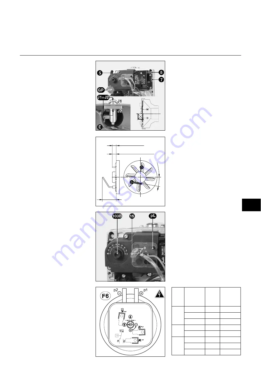
Type
Burner
Power
kW
Dimen
sion
Y
mm
Air flap
103 B
0 to 18
NC4
15
17
3.5
25
20
8
35
25
12
NC6
40
25
13
50
30
18
NC9
60
25
9
70
30
11
85
35
18
5
25
10
..2
0
°
6,5
NC 9
NC 4, NC 6
Start up
Burner start up simultaneously involves
starting up the installation by the fitter
or his representative; only he can
guarantee compliance of the boiler
house with currently accepted practices
and the regulations in force.
The fitter must first have obtained a
“certificate of conformity” provided by
the certified authority or by the network
undertaker and have leak-tested and
drained the pipework upstream from
the shut-off valve.
Preliminary checks
·
Check:
– voltage supply and compare it with
that prescribed
– polarity between phase and
neutral wire
– potential difference between earth
and neutral wire.
·
Switch off electrical supply.
·
Check there is no tension.
·
Close the gas valve.
·
Read the instructions provided by
the boiler manufacturer and that of
the heat controller.
·
Check:
– that the type of gas and the
distribution pressure are
appropriate to the burner.
– that the combustion air supply to
the boiler-house and the exhaust
pipe for the products of
combustion are compatible with
burner and fuel capacity.
– that the flue functions correctly.
Leakage test
·
Connect a pressure gauge to the
upstream pressure take-off
119
located on the valve assembly.
·
Open the shut-off valve.
·
Check the supply pressure.
·
Use a purpose-designed foam to
check the external tightness of the
valve assembly connections.
No leaks should be observed.
·
If necessary, drain the pipework
downstream from the shut-off valve.
·
Reclose the drain valve and the
shut-off valve.
Air pressure switch F6
The air pressure switch is pre-set to
10 daPa. This setting enables the
burner to be started under any
circumstances. Screw
V
can be used to
make adjustments after having checked
flow-rate and combustion test.
Settings
Combustion head:
The burner is delivered set for
natural
gases
.
To have access to the firing head:
·
Loosen the four screws
5
five turns.
·
Work the board free and pull until
completely clear.
·
Hang the board from the hanging
point
7
.
·
Loosen (clockwise) the locking nut
on the gas head.
·
Loosen completely (counterclockwise)
the spherical head screw
E
.
·
Remove the firing head.
·
Check position of the ignition
electrode, on the stop against the
gas star, and check position of the
ionization probe (see diagram).
When
propane gas
is to be used, the
GP
diffusor on the board must be fitted
to the turbulator (see Conversion).
·
Reassemble the board, following the
disassembly sequence in reverse
order.
·
When reassembling, check that the
O-ring
J2
is present and correctly
positioned.
·
Check for leaks after reassembly.
Combustion air:
Set the flap opening (
103/B
) from 0 to
18, according to the chart.
+
air =
–
CO
2
and vice-versa
with no CO production
Secondary air:
Dimension
Y
governs the secondary air
between the turbulator and the blast
tube. Setting occurs by turning the
screw
15
. Reading is by the vernier
graduated 0 to 35mm.
By increasing this value
(counter-clockwise):
–
CO
2
decreases and vice-versa
–
nominal output decreases and
vice-versa
–
start up is “harder” and vice-versa
EN
Содержание 13 009 306
Страница 14: ...01 2005 Art Nr 13 010 553B 14 ...
Страница 52: ...01 2005 Art Nr 13 010 553B 52 ...
Страница 58: ...01 2005 Art Nr 13 010 553B 58 ...
Страница 59: ...59 01 2005 Art Nr 13 010 553B ...


