CANifier
User’s
Guide www.ctr-electronics.com 10/8/2017
Cross The Road Electronics Page 11 10/8/2017
2. Installation
Below is the typical procedure for installing a CANifier.
2.1. Installing CAN Bus and Power leads
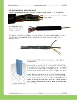
Prepare wires ahead of time to solder to CANifier.
Generally, every use case will require power and
ground wire leads, and CAN bus.
Twist/rat-tail splice two CAN pigtail wire pairs so
that it can be easily soldered. This allows for
daisy chaining of CAN bus devices.
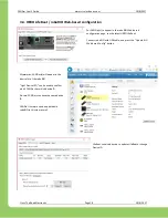
Pre-tin the stripped CAN bus and power/ground wire ends and respective
solder
pads
the CANifier.
Hold pre-tinned solder lead over the pad and apply heat via the soldering iron. Solder joint
should appear shiny after cooling with no gaps or discontinuities on the joint surface.


