CANifier
User’s
Guide www.ctr-electronics.com 10/8/2017
Cross The Road Electronics Page 12 10/8/2017
2.2. Wiring Common-Anode LED Strip
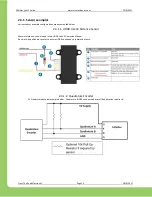
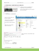
CANifier is designed to be mated directly or near-proximity to the connection point of a common-anode LED strip.
Depending on what is available on the LED strip end, an additional pin header can be solder to facilitate wiring to
the CANifier, or the LED strip can be directly soldered to the CANifier pads.
Note the signal orientation (from top to bottom) of LED Strip (Blue, Red, Green, V+) to CANifier (C, B, A, V+).
Ensure that the rail of the LED Strip connects to the V+ hole/pad on the CANifier.
Warning
: Be sure to select the proper wire gauge for the LED strip. LED strips can draw several Amperes, and
selection of a thin gauge may increase the risk of fire. PDP breakers/fuses do not improve this problem since
they do not open until 10-40A of continuous draw (depending on which fuse/breaker type). If in doubt, feel the
wire harness after several minutes of continuous use to confirm the presence of excessive heat. If excessive
heat is detected, consider using a larger gauge.
2.3. Wiring remaining signals.
Depending on use-case, additional signals may need to be wired.
The remaining signals that can be wired via the solder holes are
…
-
Quadrature Encoder.
-
I2C.
-
SPI.
-
PWM (input and output).
-
Limit Switches.
-
3.3V/5V/GND for peripherals powered by CANifier.
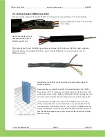
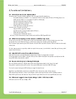
Strip ~20AWG wire and pass thru the
100mil through-holes. Apply sufficient
solder on opposite side and flush-cut the
excess stripped wire.
Alternatively, a 100-mil spaced header
could be soldered on for convenient
socket/breadboard reuse.
However, in a critical application (mobile robotics for example) a soldered connection is typically
far
more robust.


