FRM220 Chassis Quick Installation Guide
17
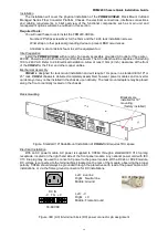
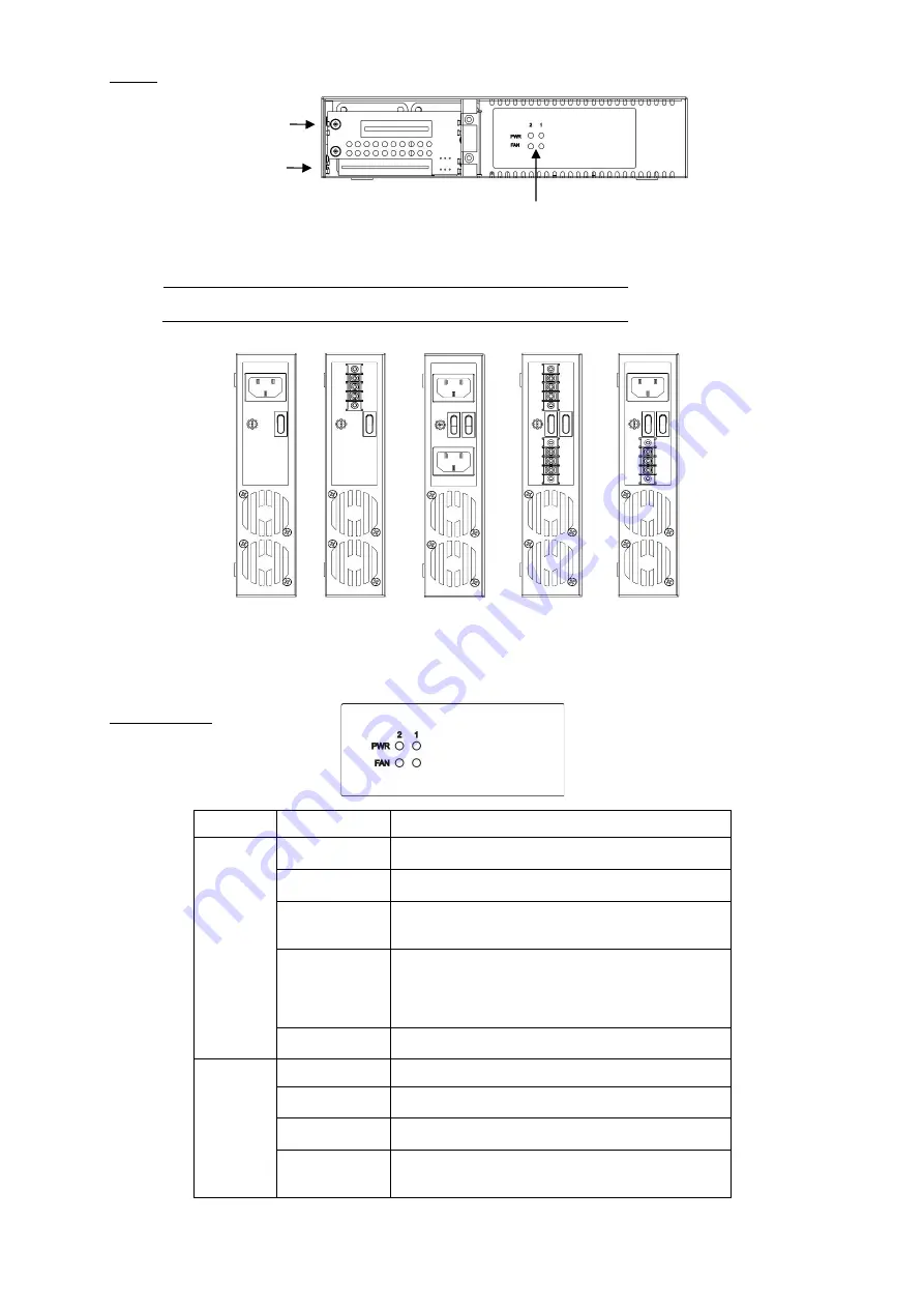
Panels
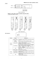
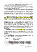
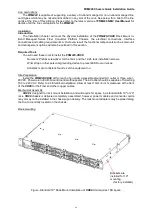
Figure. Front Panel
Note: For Telnet, Web, Console and SNMP management, NMC
card must be inserted in Slot 2.
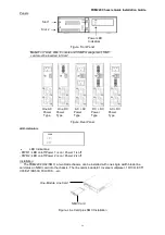
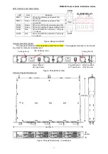
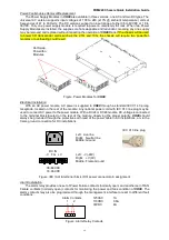
Figure. Rear Panel
LED Indicators
LED
Status
Definition
PWR1
PWR2
Steady Green
The chassis receives power current from power
1 or 2.
Green
Blinking
Power current is zero (in standby mode).
Steady Red
Power voltage is smaller than 9V or power
current is over 2500 mA.
(Voltage < 9V or Current > 2500 mA)
Red Blinking
Power voltage is larger than 10.5V but smaller
than 9V or power current is larger than "2500 *
90% mA" but smaller than 2500 mA.
(10.5V < Voltage < 9V or 2500 * 90% mA <
Current < 2500 mA)
Off
Turn off the PWR 1 or 2 LED indicator via the
NMC card.
FAN1
FAN2
Steady Green Fan is working normally.
Red Blinking
Current fan speed (RPM) is slow than "fan
speed * 60%".
Steady Red
Current fan speed (RPM) is slow than "fan
speed * 20%.
Off
- Power current is smaller than 300 mA. (in Auto
Sensor mode)
- Fan is off or not working.
Slot 1
Slot 2
Power & FAN
LED Indicators
DC + DC
Power
Type
AC + AC
Power
Type
AC + DC
Power
Type
One DC
Power
Type
One AC
Power
Type


