background image

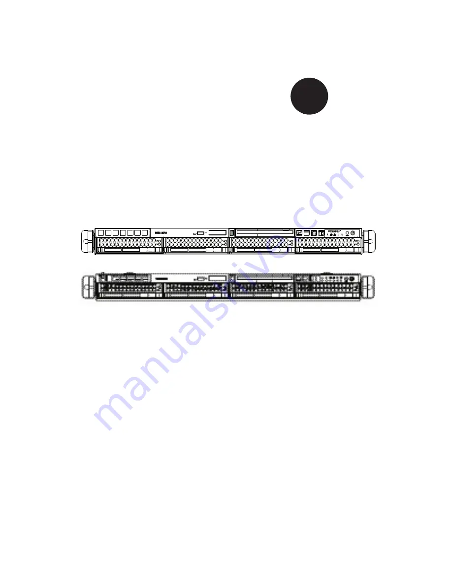
SC815 Chassis Series


SC815TQ-700(V)(B)

SC815S-700(V)(B)

SC815TQ-700C(V)(B)

SC815S-700C(V)(B)

SC815TQ-R650C(V)(B)

SC815S-R650C(V)(B)

SC815TQ-560(V)(B)

SC815S-560(V)(B)

SC815TQ-560C(V)(B)

SC815S-560C(V)(B)

SC815TQ-R650U(V)(B)

SC815TQ-R450U(V)(B)

SC815TQ-560U(V)(B)

SC815TQ-710U(B)

SC815TQ-710(V)(B)

SC815TQ-710C(V)(B)


USER’S MANUAL 

1.1


S

UPER

®

Summary of Contents for SC815S-560B

Page 1: ...C815TQ 700C V B SC815S 700C V B SC815TQ R650C V B SC815S R650C V B SC815TQ 560 V B SC815S 560 V B SC815TQ 560C V B SC815S 560C V B SC815TQ R650U V B SC815TQ R450U V B SC815TQ 560U V B SC815TQ 710U B SC815TQ 710 V B SC815TQ 710C V B USER S MANUAL 1 1 SUPER ...

Page 2: ...ive venue for the resolution of any such disputes Super Micro s total liability for all claims will not exceed the price paid for the hardware product FCC Statement This equipment has been tested and found to comply with the limits for a Class A digital device pursuant to Part 15 of the FCC Rules These limits are designed to provide reasonable protection against harmful interference when the equip...

Page 3: ...ures a unique and highly optimized design for dual core Xeon platforms The chassis is equipped with a 710W 700W 650W 560W or 450W high efficiency power supply for superb power savings High perfor mance fans provide ample optimized cooling for FB DIMM memory modules and 4 hot swappable drive bays offers maximum storage capacity in a 1U form factor This document lists compatible parts available when ...

Page 4: ...udes the functions and information provided by the control panel on the chassis as well as other LEDs located throughout the system Chapter 5 Chassis Setup and Installation Refer to this chapter for detailed information on this chassis You should follow the procedures given in this chapter when installing removing or reconfiguring your chassis Chapter 6 Rack Installation Refer to this chapter for d...

Page 5: ... Safety 2 1 Overview 2 1 2 2 Warnings and Precautions 2 1 2 3 Preparing for Setup 2 1 2 4 Electrical Safety Precautions 2 2 2 5 General Safety Precautions 2 3 2 6 System Safety 2 3 Chapter 3 Chassis Components 3 1 Overview 3 1 3 2 Components 3 1 Chassis 3 1 Backplane 3 1 Fans 3 1 Mounting Rails 3 1 Power Supply 3 2 Air Shroud 3 2 3 3 Where to get Replacement Components 3 2 Chapter 4 System Interfa...

Page 6: ...ing the Motherboard 5 8 Permanent and Optional Standoffs 5 8 Expansion Card Setup 5 10 5 7 Installing the Air Shroud 5 12 5 8 System Fans 5 14 5 9 Power Supply 5 16 Power Supply Failure 5 16 Chapter 6 Rack Installation 6 1 Overview 6 1 6 2 Unpacking the System 6 1 6 3 Preparing for Setup 6 1 Choosing a Setup Location 6 1 Rack Precautions 6 2 General Server Precautions 6 2 Rack Mounting Considerati...

Page 7: ...vii Preface Appendix A SC815 Chassis Cables Appendix B SC815 Power Supply Specifications Appendix C BPN SAS 815TQ Backplane Specifications Appendix D BPN SCA 813S Backplane Specifications ...

Page 8: ...SC815 Chassis Manual viii Notes ...

Page 9: ... I O Slots Power Supply SC815TQ 710UB DP Dual core Xeon 4x SAS SATA 2x FH 1x LP 710W DC SC815TQ 710V SC815TQ 710B DP Dual core Xeon 4x SAS SATA 1x FF 1x LP 710W DC SC815S 710CV SC815S 710CB DP Dual core Xeon 4x U320 SCSI 1x FF 710W DC SC815TQ 700V SC815TQ 700B DP Dual core Xeon 4x SAS SATA 1x FF 1x LP 700W SC815TQ 700CV SC815TQ 700CB DP Dual core Xeon 4x SAS SATA 1x FF 700W SC815S 700V SC815S 700B...

Page 10: ...P Dual core Xeon 4x SAS SATA 1x FF 1x LP 560W SC815TQ 560CV SC815TQ 560CB DP Dual core Xeon 4x SAS SATA 1x FF 560W SC815S 560V SC815S 560B DP Dual core Xeon 4x U320 SCSI 1x FF 1x LF 560W SC815S 560CV SC815S 560CB DP Dual core Xeon 4x U320 SCSI 1x FF 560W SC815TQ R450UV SC815TQ R450UB UP Dual core Xeon 4x SAS SATA 2x FH 1x LP 450W Re dundant ...

Page 11: ...E SCSI or SES2 SAS SATA I O Expansion slots Each version of the SC815 Chassis includes one full I O expansion slot and one low profile I O slot C versions include only the full I O expansion slot U versions are optimized for UIO mother boards and include two full I O expansion slots and one low profile expansion slot Peripheral Drives Each SC815 Chassis supports one slim DVD ROM Drive included and o...

Page 12: ...dress Super Micro Computer B V Het Sterrenbeeld 28 5215 ML s Hertogenbosch The Netherlands Tel 31 0 73 6400390 Fax 31 0 73 6416525 Email sales supermicro nl General Information support supermicro nl Technical Support rma supermicro nl Customer Support Asia Pacific Address Super Micro Computer Inc 4F No 232 1 Liancheng Rd Chung Ho 235 Taipei County Taiwan R O C Tel 886 2 8226 3990 Fax 886 2 8226 399...

Page 13: ... must be mailed when service is complete For faster service RMA authorizations may be requested online http www supermicro com support rma Whenever possible repack the chassis in the original Supermicro carton using the original packaging material If these are no longer available be sure to pack the chassis securely using packaging material to surround the chassis so that it does not shift within ...

Page 14: ...SC815 Chassis Manual 1 6 Notes ...

Page 15: ...aim with carrier who delivered your system Decide on a suitable location for the rack unit that will hold that chassis It should be situated in a clean dust free area that is well ventilated Avoid areas where heat electrical noise and electromagnetic fields are generated You will also need it placed near at least one grounded power outlet When con figured the SC815 chassis includes one power supply ...

Page 16: ... is fa miliar with the power off controls should be nearby to switch off the power if necessary Use only one hand when working with powered on electrical equipment This is to avoid making a complete circuit which will cause electrical shock Use extreme caution when using metal tools which can easily damage any electrical components or circuit boards they come into contact with Do not use mats desi...

Page 17: ...here power is present After accessing the inside of the system close the system back up and secure it to the rack unit with the retention screws after ensuring that all connections have been made 2 6 System Safety Electrostatic discharge ESD is generated by two objects with different electrical charges coming into contact with each other An electrical discharge is created to neutralize this differ...

Page 18: ...a wrist strap Handle a board by its edges only do not touch its components peripheral chips memory modules or contacts When handling chips or modules avoid touching their pins Put the serverboard and peripherals back into their antistatic bags when not in use For grounding purposes make sure your computer chassis provides excellent conductivity between the power supply the case the mounting fasten...

Page 19: ...icro com This chassis accepts a 1U backplane four fans with an optional fifth fan and one sometimes two power supplies SC815 models come in silver and black Backplane Each SC815 chassis comes with a 1U backplane Depending on our order you backplane will accept SAS SATA or SCSI For more information regarding compat ible backplanes view the appendices found at the end of this manual In addition visit...

Page 20: ...stic that funnel air directly to where it is needed Always use the air shroud included with your chassis 3 3 Where to get Replacement Components Though not frequently you may need replacement parts for your system To en sure the highest level of professional service and technical support we strongly recommend purchasing exclusively from our Supermicro Authorized Distributors System Integrators Res...

Page 21: ...view There are several LEDs on the control panel and on the drive carriers that provide system and component status This chapter explains the meanings of all LED indi cators and the appropriate responses that need to be taken Figure 4 1 Control Panel Buttons and LEDs ...

Page 22: ... system before servicing Reset The reset button is used to reboot the system 4 2 Control Panel Buttons The SC815 chassis includes two or three push buttons located on the front panel a reset button a power on off button and a UID button UID When used with a UID compatible motherboard the UID button is used to turn on or off the blue light function of the the U LED Once the blue light is activated ...

Page 23: ...installation The feature requires a motherboard that supports the Universal Information LED When this LED blinks red quickly it indicates a fan failure and when blinking red slowly a power failure This LED will be blue when used for UID Unit Identifier When on continuously red it indicates an overheat condition which may be caused by cables obstructing the airflow in the system or the ambient room t...

Page 24: ...s green LED on the front of the SATA drive carrier indicates drive activity A Power Indicates power is being supplied to the system s power supply units This LED should normally be illuminated when the system is operating HDD Indicates IDE channel activity SAS SATA drive SCSI drive and or DVD ROM drive activity when flashing NIC1 Indicates network activity on GLAN1 when flashing NIC2 Indicates netwo...

Page 25: ...d LED to indicate a drive failure If one of the SCSI drives fail you should be notified by your system management software 4 5 Power Supply LEDs and Overheat Indicators This chassis provides several options which may include hot swappable cold swappable and redundant power supplies Some power supplies include an LED in the rear with the following definitions 450W and 650W Power Supply 650W Power Sup...

Page 26: ...eating The section lists actions that should be taken in the unlikely event the server overheats Overheat Temperature Setting Some backplanes allow the overheat temperature to be set at 45 50 or 55 by changing a jumper setting For more information download the backplane user manual at www supermicro com To access the manuals on the Website click support and then click the manuals link Overheating ...

Page 27: ...4 7 Chapter 4 System Interface Check the routing of the cables and make sure all fans are present and oper ating normally Verify that the heatsinks are installed properly 3 4 ...

Page 28: ...SC815 Chassis Manual 4 8 Notes ...

Page 29: ...up your chassis 5 2 Installation Procedures Removing the Chassis Cover and Front Bezel Installing Hard Drives DVD and Floppy Drive Installation Installing the Motherboard includes U I O Slot Setup Installing the Air Shroud and Check Airflow General Maintenance General Maintenance Systems Fans General Maintenance Replace Power Supply Review the warnings and precautions listed in the manual be fore s...

Page 30: ...nce the top cover is released from the locked position slide the cover toward the rear of the chassis Lift the cover off the chassis 1 2 3 Warning Except for short periods of time do NOT operate the server without the cover in place The chassis cover must be in place to allow proper airflow and prevent overheating Figure 5 1 Removing the Chassis Cover Release Tab Remove this screw if necessary 1 3 ...

Page 31: ...oved for cleaning or replacement It is recommended that you keep a maintenance log and frequently replace the filter The filter s condition will affect the airflow throughout the whole system Removing the Front Bezel Unlock the bezel lock Press the release knob to retract the bezel pins Carefully remove the bezel with both hands 1 2 3 Front Bezel Bezel pins Release Knob Bezel Lock Figure 5 2 Removing...

Page 32: ...nstalling Hard Drives Removing Hard Drive Trays from the Chassis 1 Press the release button on the drive tray This extends the drive bay handle 2 Use the handle to pull the drive out of the chassis Figure 5 3 Removing Hard Drive 1 2 ...

Page 33: ...irflow for the drive bays Figure 5 4 Chassis Drive Tray Installing a Hard Drive to the Hard Drive Tray Remove the screws 2 holding connecting the drive tray the carrier Remove the tray from the carrier 1 2 Warning Except for short periods of time swapping hard drives do not operate the server with the hard drives empty 1 1 Figure 5 5 Removing Dummy Drive from Tray Drive Tray Dummy Drive ...

Page 34: ...wn so that the mounting holes align with those in the carrier Secure the hard drive by tightening all six 6 screws Replace the drive tray into the chassis Make sure the close the drive tray handle 3 4 5 Drive Tray SAS SATA or SCSI Hard Drive Figure 5 6 Removing Hard Drive Figure 5 7 Removing Hard Drive 4 4 5 ...

Page 35: ...or back plane If you are adding a new drive Remove the mini bezel grate from the drive bay The bezel can be removed by pulling out the hard drive beneath the DVD ROM or Floppy drive bay then pulling the mini bezel forward If you are replacing a drive Locate the locking tab at the rear left hand side when viewed from the front of the DVD Rom or floppy drive Push the tab toward the drive and push the...

Page 36: ...chassis includes permanent standoffs in locations used by most motherboards These standoffs accept the rounded Phillips head screws included in the SC815 accessories packaging Some motherboard require additional screws for heatsinks general components and or non standard security Optional standoffs are included to these mother boards To use an optional standoff you must place the hexagonal screw t...

Page 37: ...e card from the chassis As required by your motherboard install standoffs in any areas that do not have a permanent standoff To do this A Place a hexagonal standoff screw through the bottom the chassis B Secure the screw with the hexagon nut rounded side up Lay the motherboard on the chassis aligning the permanent and optional standoffs Secure the motherboard to the chassis using the rounded Phill...

Page 38: ... full height full length expansion slot and one low profile slot Note You must use a riser card to install expansion cards to any SC815 chassis Riser cards are sold separately For the latest compatibility and performance information visit our website at http www supermicro com SC815 560C SC815 560 SC815 560C Figure 5 9 SC815 Chassis Rear with One Full Height Full Length I O slot Figure 5 10 SC815 C...

Page 39: ...nformation see the riser card installation instructions Choose the I O panel in which to place the add on card In that slot open the I O panel lever and slide the I O panel sideways From inside the chassis remove the I O panel Slide the add on card into the riser card and attach the add on card bracket in place of the I O panel Secure the add on card by closing the I O panel lever Connect cables t...

Page 40: ...ing the Air Shroud Figure 5 11 Air Shroud Front Fan Side Optional Flap Air shrouds concentrate airflow to maximize fan efficiency The SC815 chassis air shroud does not require screws to set up Figure 5 12 Air Shroud without the Otional Flap ...

Page 41: ...in your chassis with the fan side touching the edge of the fans Replace the chassis cover 1 2 3 4 Checking the Server s Air Flow Make sure there are no objects to obstruct airflow in and out of the server In addition if you are using a front bezel make sure the bezel s filter is replaced periodically Do not operate the server without drives or drive trays in the drive bays Use only recommended serve...

Page 42: ...at provide an additional open fan housing an additional system fan may be added for optimal cooling Adding a System Fan Turn off the power to the system and unplug the system from the outlet Remove the dummy fan from the fan tray Place the new fan into the vacant space in the housing while making sure the arrows on the top of the fan indicating air direction point in the same direc tion as the arr...

Page 43: ...ssis open Turn off the power to the system and unplug the system from the outlet Remove the failed fan s power cord from the serverboard Lift the failed fan from the chassis and pull it completely out from the serverboard Place the new fan into the vacant space in the housing while making sure the arrows on the top of the fan indicating air direction point in the same direc tion as the arrows on t...

Page 44: ...ll be illuminated on the power supply when the power is off An il luminated green light indicates that the power supply is operating Power Supply Failure If the power supply unit fails the system will shut down and you will need to replace the unit Replacement units can be ordered directly from Supermicro see contact information in the Preface As there is only one power supply unit in the SC815 Ch...

Page 45: ...er running and remove only one power supply Push the release tab on the back of the power supply as illustrated Pull the power supply out using the handle provided Replace the failed power module with the same model Push the new power supply module into the power bay until you hear a click Plug the AC power cord back into the module and power up the server 1 2 3 4 5 6 Figure 5 15 Removing the Powe...

Page 46: ...SC815 Chassis Manual 5 18 Notes ...

Page 47: ...al noise and electromagnetic fields are generated You will also need it placed near a grounded power outlet Be sure to read the Rack and Server Precautions in the next section 6 3 Preparing for Setup The box your chassis was shipped in should include two sets of rail assemblies two rail mounting brackets and the mounting screws you will need to install the system into the rack Please read this sect...

Page 48: ... General Server Precautions Review the electrical and general safety precautions that came with the com ponents you are adding to your chassis Determine the placement of each component in the rack before you install the rails Install the heaviest server components on the bottom of the rack first and then work up Use a regulating uninterruptible power supply UPS to protect the server from power surg...

Page 49: ...mised Mechanical Loading Equipment should be mounted into a rack so that a hazardous condition does not arise due to uneven mechanical loading Circuit Overloading Consideration should be given to the connection of the equipment to the power supply circuitry and the effect that any possible overloading of circuits might have on overcurrent protection and power supply wiring Appropriate consideratio...

Page 50: ... with the rack unit you are using NOTE This rail will fit a rack between 26 and 33 5 deep Identifying the Sections of the Rack Rails The chassis package includes two rack rail assemblies in the rack mounting kit Each assembly consists of two sections an inner fixed chassis rail that secures directly to the server chassis and an outer fixed rack rail that secures directly to the rack itself Figure 6 1...

Page 51: ...e pre attached inner rail Slide the extension toward the front of the chassis Secure the chassis with 2 screws as illustrated Repeat steps 1 3 for the other inner rail extension 1 2 3 4 Inner Rail Extension The SC815 chassis includes a set of inner rails in two sections inner rails and inner rail extensions The inner rails are pre attached and do not interfere with normal use of the chassis if you...

Page 52: ...h the short and long brackets to the proper distance so that the rail fits snugly into the rack Secure the long bracket to the front side of the outer rail with two M5 screws and the short bracket to the rear side of the outer rail with three M5 screws Repeat steps 1 4 for the left outer rail 1 2 3 4 Secure to the Front of the Rack Secure to the Rear of the Rack Figure 6 3 Assembling the Outer Rail...

Page 53: ...6 7 Chapter 6 Rack Installation SCALE 0 380 Figure 6 4 Installing the Outer Rails to the Server Rack 2 3 3 ...

Page 54: ...on the rack Line chassis rails A and B with the front of the rack rails C Slide the chassis rails into the rack rails keeping the pressure even on both sides you may have to depress the locking tabs when inserting When the server has been pushed completely into the rack you should hear the locking tabs click Optional Insert and tightening the thumbscrews that hold the front of the server to the ra...

Page 55: ...If you are installing the SC815 chassis into a Telco type rack follow the directions given on the previous pages for rack installation The only difference in the installa tion procedure will be the positioning of the rack brackets to the rack They should be spaced apart just enough to accommodate the width of the Telco rack ...

Page 56: ...SC815 Chassis Manual 6 10 Notes ...

Page 57: ...e 9 8 pin to 8 pin ribbon cable for SGPIO CBL 0087 Round Ribbon Cable 20 16 pin to 16 pin ribbon cable for control panel CBL 0139L Braid Ribbon Cable 50 cm IDE 80 Wire cable for DVD ROM Cable 6 Regional power cord CBL 0180L 01 SATA Set various SATA Set of 70 59 48 38cm Round Cables SC815TQ 710 Part Type Length Description CBL 0157L Round Ribbon Cable 9 8 pin to 8 pin ribbon cable for SGPIO CBL 008...

Page 58: ...ble for DVD ROM Cable 6 Regional power cord CBL 0180L 01 SATA Set various SATA Set of 70 59 48 38cm Round Cables SC815TQ R650 Part Type Length Description CBL 0157L Round Ribbon Cable 9 8 pin to 8 pin ribbon cable for SGPIO CBL 0087 Ribbon Round Cable 20 16 pin to 16 pin ribbon cable for control panel CBL 0139L Braid Ribbon Cable 50 cm IDE 80 Wire cable for DVD ROM Cable 6 Regional power cord CBL ...

Page 59: ...C815S 700 Part Type Length Description CBL 033L U320 Round Ribbon Cable 9 ULTRA 320 cable CBL 0087 Ribbon Round Cable 20 16 pin to 16 pin ribbon cable for control panel CBL 0139L Braid Ribbon Cable 50 cm IDE 80 Wire cable for DVD ROM Cable 6 Regional power cord SC815S R650 Part Type Length Description CBL 033L U320 Round Ribbon Cable 9 ULTRA 320 cable CBL 0087 Ribbon Round Cable 20 16 pin to 16 pi...

Page 60: ... 0175L Alt Name Big Four Alternate SAS SATA Cables Some compatible motherboards have different connectors If your motherboard has only one SAS connector that the SAS SATA cables must share use one of the following cables These cables must be purchased separately Description This cable has one ipass SFF 8087 mini sas connector 36 pins at one end and 4 SAS connectors on one end This cable connects f...

Page 61: ...n CBL 0059 7 9 20 CM 8 pin CBL 0062 7 9 20 CM 4 pin CBL 0060 7 9 20 CM Front Panel to the Motherboard The SC815 chassis includes a cable to connect the chassis front panel to the motherboard If your motherboard uses a different connector use the following list to find a compatible cable Front Panel to Motherboard Cable Ribbon Cable Number of Pins Front Panel Number of Pins Motherboard Cable Part 16...

Page 62: ...SC815 Chassis Manual A 6 Notes ...

Page 63: ...WS 651 1R PWS 561 1H20 PWS 561 1H Rated AC Volt age 100 240V 50 60Hz 24 11 Amp 100 240V 50 60Hz 10 4 Amp 100 240V 50 60Hz 8 4 Amp 100 240V 50 60Hz 8 5 4 Amp 100 240V 50 60Hz 8 5 4 Amp 5V standby 4 Amp 4 Amp 3 Amp 3 Amp 3 Amp PDB 12V 59 Amp 57 Amp 54 Amp 43 6 Amp 43 6 Amp 5V 24 Amp 30 Amp 25 Amp 25 Amp 25 Amp 3 3V 21 Amp 24 Amp 12 Amp 21 Amp 21 Amp 12V 0 6 Amp 0 6 Amp 0 5 Amp 0 6 Amp 0 6 Amp PDB Po...

Page 64: ...SC815 Chassis Manual B 2 Notes ...

Page 65: ...es only do not touch its components peripheral chips memory modules or gold contacts When handling chips or modules avoid touching their pins Put the card and peripherals back into their antistatic bags when not in use C 2 General Safety Guidelines Always disconnect power cables before installing or removing any components from the computer including the SAS 825TQ Backplane Disconnect the power ca...

Page 66: ...T0 ACT1 JTAG UPGRADE JP29 9071 RST JP18 BUZZER RESET ACT2 ACT3 SIDEBAND M9 M15 JP10 D3 JP18 J8 J7 J6 J5 JP29 JP44 R144 MH2 M46 J9 J10 JP26 JP47 JP46 JP42 JP33 JP34 JP40 JP51 REV 1 00 SAS815TQ S UPER R SAS Ports Front Connectors Jumper Settings and Pin Definitions C 4 Front Connectors and Jumpers 1 Power Connectors 4 pin JP10 2 CD ROM Floppy Drive Power J9 and J10 3 JTAG JP47 4 Upgrade Pin JP46 5 MG...

Page 67: ...should be used by a certified and experienced technician Backplane Main Power 4 Pin Connector JP10 Pin Definition 1 12V 2 and 3 Ground 4 5V 1 Backplane Main Power Connectors The 4 pin connectors designated JP10 provide power to the backplane See the table on the right for pin definitions 2 CD ROM Floppy 4 Pin Connectors The 4 pin connectors designated J9 and J10 provide power to the CD ROM and floppy...

Page 68: ...o monitor HDD activity and status See the table on the right for pin definitions I2 C Connector Pin Definitions JP44 Pin Definition 1 Data 2 Ground 3 Clock 4 No Connection SAS Activity LED Header Pin Definitions JP26 Pin Definition Pin Definition 1 ACT IN 0 6 ACT IN 4 2 ACT IN 1 7 ACT IN 5 3 ACT IN 2 8 ACT IN 6 4 ACT IN 3 9 ACT IN 7 5 Ground 10 Empty 8 Activity LED Header The activity LED header designa...

Page 69: ...umper Jumper Settings Note JP18 Open Enabled Closed Disabled Buzzer Reset JP29 Open Default Closed Reset MG 9071 Chip Reset 5V GND GND 12V 2 I C 5V 12V 5V 12V 1 2 3 0 ACT IN ACT0 ACT1 JTAG UPGRADE JP29 9071 RST JP18 BUZZER RESET ACT2 ACT3 SIDEBAND M9 M15 JP10 D3 JP18 J8 J7 J6 J5 JP29 JP44 R144 MH2 M46 J9 J10 JP26 JP47 JP46 JP42 JP33 JP34 JP40 JP51 REV 1 00 SAS815TQ S UPER R 2 I C 5V 12V 1 2 0 ACT ...

Page 70: ...Setting Jumper Jumper Setting Note JP33 1 2 Controller ID JP34 1 2 ID 0 Backplane ID JP40 Closed I2 C Reset SD OUT JP42 1 2 Backplane ID SDIN JP50 Open I2 C Reset 5V GND GND 12V 2 I C 5V 12V 5V 12V 1 2 3 0 ACT IN ACT0 ACT1 JTAG UPGRADE JP29 9071 RST JP18 BUZZER RESET ACT2 ACT3 SIDEBAND M9 M15 JP10 D3 JP18 J8 J7 J6 J5 JP29 JP44 R144 MH2 M46 J9 J10 JP26 JP47 JP46 JP42 JP33 JP34 JP40 JP51 REV 1 00 SA...

Page 71: ...nector Connector Number SAS Drive Number SAS 0 J1 SAS SATA HDD 0 SAS 1 J2 SAS SATA HDD 1 SAS 2 J3 SAS SATA HDD 2 SAS 3 J4 SAS SATA HDD 3 D12 D5 SAS D13 D6 SAS SAS SAS D14 D7 D15 D8 Rear LED Indicators Rear Connector Hard Drive Activity Failure LED SAS 0 D12 D5 SAS 1 D13 D6 SAS 2 D14 D7 SAS 3 D15 D8 ...

Page 72: ...atic discharge Touch a grounded metal object before removing a component from the antistatic bag Handle the RAID card by its edges only do not touch its components peripheral chips memory modules or gold contacts When handling chips or modules avoid touching their pins Put the card and peripherals back into their antistatic bags when not in use D 2 General Safety Guidelines Always disconnect power...

Page 73: ...t Note to Users All images and layouts shown in this user s guide are based upon the latest PCB Revision available at the time of publishing The card you have received may or may not look exactly the same as the graphics shown in this manual ...

Page 74: ...LVD1 BZ1 OFF DISABLE ON ENABLE JP17 BUZZER ENABLE REV 1 03 UPER S SCA813S R Front Connectors Jumper Settings and Pin Definitions D 4 Front Connectors and Jumpers 1 Backplane Main 4 Pin PWR JP10 2 GEM 318 Chip 3 CD ROM Floppy Drive 4 Pin PWR Connector J1 and J2 4 SCSI Channel LVD1 3 1 2 4 ...

Page 75: ...Power 4 Pin Connector J1 and J2 Pin Definition 1 5V 2 and 3 Ground 4 12V 2 GEM Chip SAF TE SCSI Accessed Fault Tolerant Enclosures The GEM chip allows the system to monitor the status of the disk drives and provides disk drive information to the user through the LED indicators and buzzers This function is only available when a RAID controller with a Raid set is present and enabled SAF TE LED Indica...

Page 76: ...DB 6 13 DB 7 47 DB 7 14 DB P 48 DB P 15 Ground 49 Ground 16 DIFFSENS 50 Ground 17 TERMPWR 51 TERMPWR 18 TERMPWR 52 TERMPWR 19 Reserved 53 Reserved 20 Ground 54 Ground 21 ATN 55 ATN 22 Ground 56 Ground 23 BSY 57 BSY 24 ACK 58 ACK 25 RST 59 RST 26 MSG 60 MSG 27 SEL 61 SEL 28 C D 62 C D 29 REQ 63 REQ 30 I O 64 I O 31 DB 8 65 DB 8 32 DB 9 66 DB 9 33 DB 10 67 DB 10 34 DB 11 68 DB 11 4 Ultra 320 SCSI Co...

Page 77: ... change the function of the connector Pin 1 is identified with a square Connector Pins Jumper Setting 3 2 1 3 2 1 Jumper Settings Jumper Jumper Settings Note JP17 Closed Enabled Open Disabled Buzzer Enable 12V 5V GND 5V 12V GND GND 5V 12V GND J2 J1 JP17 D4 U 1 M T 2 LVD1 BZ1 OFF DISABLE ON ENABLE JP17 BUZZER ENABLE REV 1 03 UPER S SCA813S R 12V 5V GND 5V 12V GND J2 J1 JP17 D4 U 1 M T 2 LVD1 BZ1 OFF...

Page 78: ...ar Connectors and LED Indicators Rear SCA Connectors Rear Connector Connector Number SCA Drive Number SCA 1 0 SCA HDD 0 SCA 3 1 SCA HDD 1 SCA 4 2 SCA HDD 2 SCA 2 3 SCA HDD 3 Rear LED Indicators Rear LED Connector Number Hard Drive Activity Failure LED SCA 1 0 D12 D5 SCA 3 1 D13 D6 SCA 4 2 D14 D16 SCA 2 3 D17 D18 ...

Page 79: ...install the drivers to your system Windows Driver Installation Procedure A Right click on My Computer and choose Properties Select Hardware tab and click Device Manager Open Other Devices or wherever GEM318 is located Right click on this device and choose Properties Click on Driver tab and choose Update Driver Click Next twice uncheck both Floppy disk drives and CD ROM drives Select Specify a loca...

Page 80: ...rks uninstall both Click on Action tab and choose Scan for Hardware Changes The Hardware Wizard program should start up Click Next At the first prompt choose Display a list of known device drivers for the device so that I can choose a specific driver and click Next Choose Other Devices and click Next Choose Have Disk and specify your floppy drive location in the options box Then click Next Highlight ...

Reviews: