INSTRUCTION MANUAL Digital Light Engraver
6
Operation and Cleaning
Effective date
30.09.2013
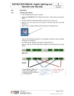
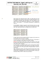
This value determines the chip width that will be used. The maximum width
is 1,024 rows. You can use the slider to determine the overlap. In this case,
the program switches off 40 micromirros on both sides of the chip and uses
944 micromirrors per row.
•
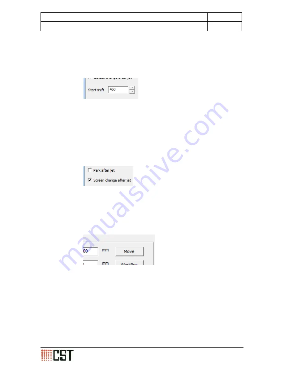
Select a value for the shift function for four colour printing jobs.
This function is recommended for four colour print jobs, especially to avoid
banding of the individual colours on the same position. The value to be en-
tered depends upon the colour. CST recommends working in increments of
222 (K = 0/C = 222/M = 444/Y = 666). When large Speed/Quality values are
to be used, you must reduce the start shift function value (200).
•
Select which final motion should occur upon completing the imaging se-
quence.
You can choose between “Park after jet” and “Screen change after jet”.
When no option is selected, the head will stop in the final position where the
previous imaging was completed.
•
Click on the "Move" button in order to move the head to the start position.
From here you can check the start position before imaging commences.
When you have entered and checked the values, start the imaging process
by clicking on the "OK" button. You can stop the imaging process by clicking
on the “cancel” button with the mouse cursor or pressing the “space bar” on
the keyboard.
CST GmbH
Königsberger Straße 117
47809 Krefeld - Germany
Page 40 of 69
Betriebsanleitung DLE-AF 01.0 engl.docx


