Crystal Vision
Virtual Cards
The next step is to fill the <controlgroup> entries with the desired controls. The process
involves copying the relevant control definition from the XML file for the 'source' card – the real
card with the real control. This definition is pasted into the appropriate control group in the
virtual card XML and changed as follows:
•
The control ID is the number right at the start of the control definition. This must be a
unique value in the virtual card, no two controls can have the same ID number. If the
virtual card contains controls from more than one real card then two might have the same
ID, by chance or because they are the same control on different cards of the same type.
One way to ensure a unique control ID is to change the ID number to a new value that
goes up by one each time you add a control. Starting at 10 avoids overlapping with the ID
numbers in the header section. Make a note of the original control ID before you overwrite
it, you will need in the next few steps.
The remaining changes take place in the 'interface' section:
•
The contents of the
'snmpcontrol'
section should be deleted. In principle you can have
SNMP control of a virtual card, but SNMP control of a user-created virtual card does not
make much sense and the file is smaller and simpler without it.
•
Change the
'controlid'
to match the number put into the 'id' in step 1.
•
Add a 'redirect' section, defined by the tags <redirect> </redirect>. The redirect section tells
the frame which slot the real control is in and what its control number is.
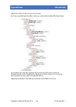
For example, using the MultiLogo ‘Play Mode’ control 170 in slot 4:
Before
After
<interface>
<controlid>75</controlid>
<snmpcontrol> <id>75</id>
<snmptableid>2</snmptableid>
<snmptrap>
<snmptraponupdate/>
</snmptrap>
</snmpcontrol>
</interface>
<interface>
<controlid>10</controlid>
number changed to match new id
<redirect>
<slotid>4</slotid>
the slot number of the source card (1-
12 in a 2U frame)
<destid>170</destid>
the control ID of the copied control
as it appears on the source card
</redirect>
</interface>
The
slotid
is the slot number that the source card is in. In a 2U frame this will be in the range 1
to 12, in a 1U frame it will be in the range 1 to 6.
The
'destid'
is the 'id' value of the control as it appears on the source card. This is the number
that you made a note of in step 1.
Apart from changing the ID number and the interface section, the control should remain as
copied from the source card file.
Indigo 2AE and 2SE User Manual R1.17
43
27 February 2020


