Crystal Vision
Installation
Note:
The total current available from the 5.3V dc outputs is limited to approximately 1.5 Amps.
To maintain EMC compliance only good quality screened cable assemblies should be used.
Note:
Serial RS422 control from third party applications is no longer supported. All
connections should be made via Ethernet.
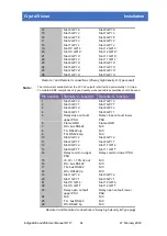
Power supply relay connections
The power supply module has a changeover relay to indicate if the frame is in an alarm state
caused by a power supply problem, a fan stopping or an overheating frame.
Upper Power Supply Relay Connections:
Description
Pin number
relay common
Remote 2 pin 14
open on fault
Remote 2 pin 23
close on fault
Remote 2 pin 5
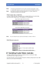
Lower Power Supply Relay Connections:
Description
Pin number
relay common
Remote 4 pin 14
open on fault
Remote 4 pin 23
close on fault
Remote 4 pin 5
Note:
The current though the relay contacts should be limited to a maximum of 200mA.
RJ45 Ethernet connector
Pin number Function
1
TD+
2
TD-
3
RD+
4 and 5
Not used – 75 ohm resistor to GND in frame
6
RD-
7 and 8
Not used – 75 ohm resistor to GND in frame
2.7 Installing Crystal Vision modules
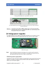
The Indigo 2AE/2SE frame has 12 slots for Crystal Vision video or audio cards. Signal
connections are made through rear modules.
The inside of the frame can be accessed to change the modules by pulling forward the two black
knobs, one on each side of the front panel.
Indigo 2AE and 2SE User Manual R1.17
15
27 February 2020


