background image


Crown Broadcast    


Phone: 574-262-8900 

2524 Toledo Road    


Fax: 574-970-8909 

Elkhart, IN 46516    


Service: 866-262-8917 

U.S.A.  


[email protected]


12 

2.2   Chassis and board mounting 


2.2.1 Mounting the RJ-45 into the chassis  

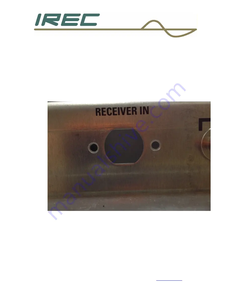
A) Locate the black colored hole plug on the back panel under the 
label [RECEIVER IN] and remove it. 
B) Use a 1/8” drill bit and drill two holes centered exactly 0.175” 
from the edge of the hole to the left and right of the hole, centered 
vertically to the hole as shown below.  

C) These two holes will match the mounting holes contained on 
the RJ-45 cable assembly.  
D) Clean up any extra metal shavings that may have fallen into the 
unit with a vacuum.  
 

Содержание IReC-1

Страница 1: ...Crown Broadcast Phone 574 262 8900 2524 Toledo Road Fax 574 970 8909 Elkhart IN 46516 Service 866 262 8917 U S A service irec1 com 1 IReC 1 Internet Remote Control Users Manual and Installation Guide...

Страница 2: ...Crown Broadcast Phone 574 262 8900 2524 Toledo Road Fax 574 970 8909 Elkhart IN 46516 Service 866 262 8917 U S A service irec1 com 2 REVISION NUMBER DATE DESCRIPTION 1 0 JUNE 2017 INITIAL RELEASE...

Страница 3: ...RING THE UNIT FOR INSTALLATION 8 SECTION 2 2 CHASSIS AND BOARD MOUNTING 12 SECTION 2 3 WIRING THE CONNECTIONS TO THE MOTHERBOARD 22 SECTION 2 4 INITIAL POWER UP 30 SECTION 2 5 INSTALLING TOP COVER PRO...

Страница 4: ...Crown Broadcast Phone 574 262 8900 2524 Toledo Road Fax 574 970 8909 Elkhart IN 46516 Service 866 262 8917 U S A service irec1 com 4 Chapter 1 Unpacking and getting started...

Страница 5: ...emblies and CD Open the package to be sure the following items are included A Board IReC 1 B Wire assemblies 1 Power with extra header 2 Flat ribbon cable 3 RJ 45 Male to Female Ethernet cable 4 Small...

Страница 6: ...portions of instructions will be necessary during the process of wiring to the motherboard Crown Broadcast has made several different versions of motherboards over the years so take note of the versio...

Страница 7: ...Crown Broadcast Phone 574 262 8900 2524 Toledo Road Fax 574 970 8909 Elkhart IN 46516 Service 866 262 8917 U S A service irec1 com 7 Chapter 2 Installation...

Страница 8: ...ng the unit for installation The unit will need to be disconnected from the power source and load and should be on a large lat surface Remove the top cover and screws and set aside The RJ 45 cable wil...

Страница 9: ...f the unit has a tuner the tuner antenna connection will need to be changed to one of the unused BNC connectors that are on the back panel If the unit does not have a tuner skip to section 2 2 Careful...

Страница 10: ...khart IN 46516 Service 866 262 8917 U S A service irec1 com 10 If the composite connector will not be used unsolder the wires from that connector and ty wrap to the others as shown below Then solder t...

Страница 11: ...hoice of connectors will be one of the three used for SCA inputs It is recommended to use the farthest one from the tuner to avoid interference with the cabling installation later This will require th...

Страница 12: ...ck colored hole plug on the back panel under the label RECEIVER IN and remove it B Use a 1 8 drill bit and drill two holes centered exactly 0 175 from the edge of the hole to the left and right of the...

Страница 13: ...900 2524 Toledo Road Fax 574 970 8909 Elkhart IN 46516 Service 866 262 8917 U S A service irec1 com 13 The RJ 45 cable can now be installed into the chassis as shown below using the provided machine s...

Страница 14: ...ick or your preferred method to remove solder remove the solder in the holes of J27 along the front edge of the motherboard B Remove front panel assembly two screws along top left and right corners an...

Страница 15: ...ront panel Remove the 3 cables that attach to the front panel boards It is not necessary to disconnect the Power wires from the switches B Unsolder and remove TP2 and TP5 along the front edge of the m...

Страница 16: ...ose to the connector as possible black and red wires B Strip and tin the two open wires C Solder the black wire to the control metering board at J1 pins 9 and 10 Care should be taken to avoid melting...

Страница 17: ...262 8917 U S A service irec1 com 17 2 2 3 Mounting the board into the unit The board hardware can now be mounted Remove the 4 screws that hold down the control meter board Or if the unit has the mete...

Страница 18: ...vice 866 262 8917 U S A service irec1 com 18 For units that have the metering board separate install 4 hex stand off bolts For units which have the metering contained on the motherboard install all 8...

Страница 19: ...2 8917 U S A service irec1 com 19 Install the board on top of the stand off bolts and use the provided hardware to secure it to the posts 6 32 x 5 16 SEMS lat washer as shown below It may be necessary...

Страница 20: ...e 574 262 8900 2524 Toledo Road Fax 574 970 8909 Elkhart IN 46516 Service 866 262 8917 U S A service irec1 com 20 Plug the power wire assembly into the motherboard header at location J27 and into the...

Страница 21: ...n based on the revision of the motherboard For motherboard revision of 2007 install cable on J1A with pin 1 red stripe toward the center of the unit All other motherboard revision levels will install...

Страница 22: ...22 2 3 Wiring the connections to the motherboard 2 3 1 Removing jumpers For motherboard revisions 2005 2006 and 2007 locate and remove all header jumpers on Z15 through Z22 The jumpers will be in dif...

Страница 23: ...erboard revision 2007 install the other end of the lat grey ribbon cable to the now empty dual row header with pin 1 red stripe on Z15 as shown below NOTE The lat ribbon cable has more sockets 20 pins...

Страница 24: ...erboard revisions 2005 and 2006 install the other end of the lat grey ribbon cable to the now empty dual row header with pin 1 red stripe on Z15 as shown below NOTE The lat ribbon cable has more socke...

Страница 25: ...as possible to the end of the connector using a pair of scissors Cut strip and tin the following wire numbers as shown below Pin 1 is the red stripe and increases away from the red stripe in numerical...

Страница 26: ...970 8909 Elkhart IN 46516 Service 866 262 8917 U S A service irec1 com 26 Pin 1 left side of R24 Pin 3 left side of R23 Pin 5 left side of R22 Pin 7 left side of R21 Pin 9 left side of R20 Pin 11 left...

Страница 27: ...2524 Toledo Road Fax 574 970 8909 Elkhart IN 46516 Service 866 262 8917 U S A service irec1 com 27 2 3 5 Installation of small signal cable Obtain the small signal cable 6 pin red connector with wires...

Страница 28: ...ing locations see illustrations below Colors of cable may not match Pin 1 Green left side of R46 Pin 2 Red left side of R50 Pin 3 Blue back side of R9 Pin 4 Purple back side of R13 Pin 5 White right s...

Страница 29: ...Elkhart IN 46516 Service 866 262 8917 U S A service irec1 com 29 Pin 5 not used cut stripped end off if applicable Pin 6 back side of R14 2 3 6 Connection to computer board with RJ 45 cable Plug the...

Страница 30: ...connections install power source and power unit up without carrier Observe red and green LED s on the computer board The red LED should illuminate continuously and the green should lash on and off ev...

Страница 31: ...top cover directly over the computer board The cardboard piece has one side with double sided tape on it Use this side to attach to top cover after removing the backing darker colored piece that is sm...

Страница 32: ...Crown Broadcast Phone 574 262 8900 2524 Toledo Road Fax 574 970 8909 Elkhart IN 46516 Service 866 262 8917 U S A service irec1 com 32 Chapter 3 Imbedded website...

Страница 33: ...on the computer being used to connect to this site Follow the computer operating system manual instructions of the computer being used to connect to the unit for installing this certi icate properly...

Страница 34: ...y default log in credentials User admin password admin This will allow connection to the unit with Administrator privileges This is necessary to allow for changes needed to the log in credentials expl...

Страница 35: ...r logging in When the Forgot Password link is chosen the user name needs to be entered and then click on the Send Recovery Link button as shown below An email will be sent to the address listed under...

Страница 36: ...controls that can be used to control the transmitter 3 2 1 Metering Metering is in the upper left section of the web site and shows the current metering channels and their levels For the older motherb...

Страница 37: ...d OK block to turn Red with the word FAULT in it The Silence Sensor indicator will be Green and will indicate OK during normal levels of program material When program material ceases to be present thi...

Страница 38: ...Crown Broadcast Phone 574 262 8900 2524 Toledo Road Fax 574 970 8909 Elkhart IN 46516 Service 866 262 8917 U S A service irec1 com 38...

Страница 39: ...h control can be used as a latching control ON OFF Toggle or as a momentary control Pulse time de ined which is set up in the I O section described later The factory default settings are shown 3 3 Mai...

Страница 40: ...user setup page Users set up tab will have the listings and credential levels of all users Factory default settings will show the three levels of access and each level of access Admin level access wil...

Страница 41: ...and setting areas in these pages are greyed out Monitor Only will only allow monitoring of the irst page This user cannot control the transmitter The user can view the different tabs but like the pre...

Страница 42: ...Crown Broadcast Phone 574 262 8900 2524 Toledo Road Fax 574 970 8909 Elkhart IN 46516 Service 866 262 8917 U S A service irec1 com 42...

Страница 43: ...O input output setup page allows con iguration for each metering status and control channel as well as the silence sensor and temperature alarm set points It also has a listing of the users and check...

Страница 44: ...imit 3 5 2 Channel reading calibration Each channel can also be calibrated to agree with the front panel readings A live display is shown to aid in the process of calibration This live reading assures...

Страница 45: ...Crown Broadcast Phone 574 262 8900 2524 Toledo Road Fax 574 970 8909 Elkhart IN 46516 Service 866 262 8917 U S A service irec1 com 45...

Страница 46: ...et for High Low or Exit Checking these boxes will send an email to the user listed when the conditions are satis ied as a valid alarm 3 5 4 Logging selections There is also an option for logging the s...

Страница 47: ...tion email alarm timing time zone information and unit identi ication 3 6 1 IP address con iguration settings IP con iguration matches typical IP equipment Factory default will have the IP information...

Страница 48: ...o send email alerts The SMTP server will need the name entered the port required the user name and password Authentication will need to be selected if the SMTP server requires it This sends the inform...

Страница 49: ...t to utilize this feature Fill in the appropriate sections to satisfy the Management tool being utilized for this feature Be sure to enable the feature and selections desired Be sure to click Save SNM...

Страница 50: ...period has been satis ied an email which contains the accumulated logs for the day will be sent to the designated address of the recipient Be sure to check the Enable Logging checkbox to activate this...

Страница 51: ...to select the checkbox for Enable Emailing for this feature to be enabled 3 6 6 Time Zone settings The time zone desired can be selected with a drop down menu Click on the down arrow on the right sid...

Страница 52: ...e unit identi ier can be changed by entering in the desired name below the Site ID label There is no limit to the character length so caution should be exercised in choosing the length of the site ID...

Страница 53: ...U S A service irec1 com 53 3 7 About the device The device name irmware revision level and Crown Broadcast s home web page are listed The bottom of each page also has contact information listed as wel...

Страница 54: ...or service at our discretion any product failure because of normal intended use Warranty repair can only be performed at our plant facility in Elkhart Indiana USA or at a factory authorized service d...

Страница 55: ...Crown Broadcast Phone 574 262 8900 2524 Toledo Road Fax 574 970 8909 Elkhart IN 46516 Service 866 262 8917 U S A service irec1 com 55...

Отзывы: