Page 30
IQ-USM 810
IQ Digital Processor / Digital Mixer
IQ-USM 810
Reference Manual
6 Working With IQ
This section provides additional information about
Crown’s IQ System with special guides to aid in the
installation and use of the IQ-USM 810. For more infor-
mation about any of these topics, contact the Crown
Technical Support Group (see Section 7 for contact
information).
6.1 A Closer Look at Audio Signal Wiring
6.1.1 Input
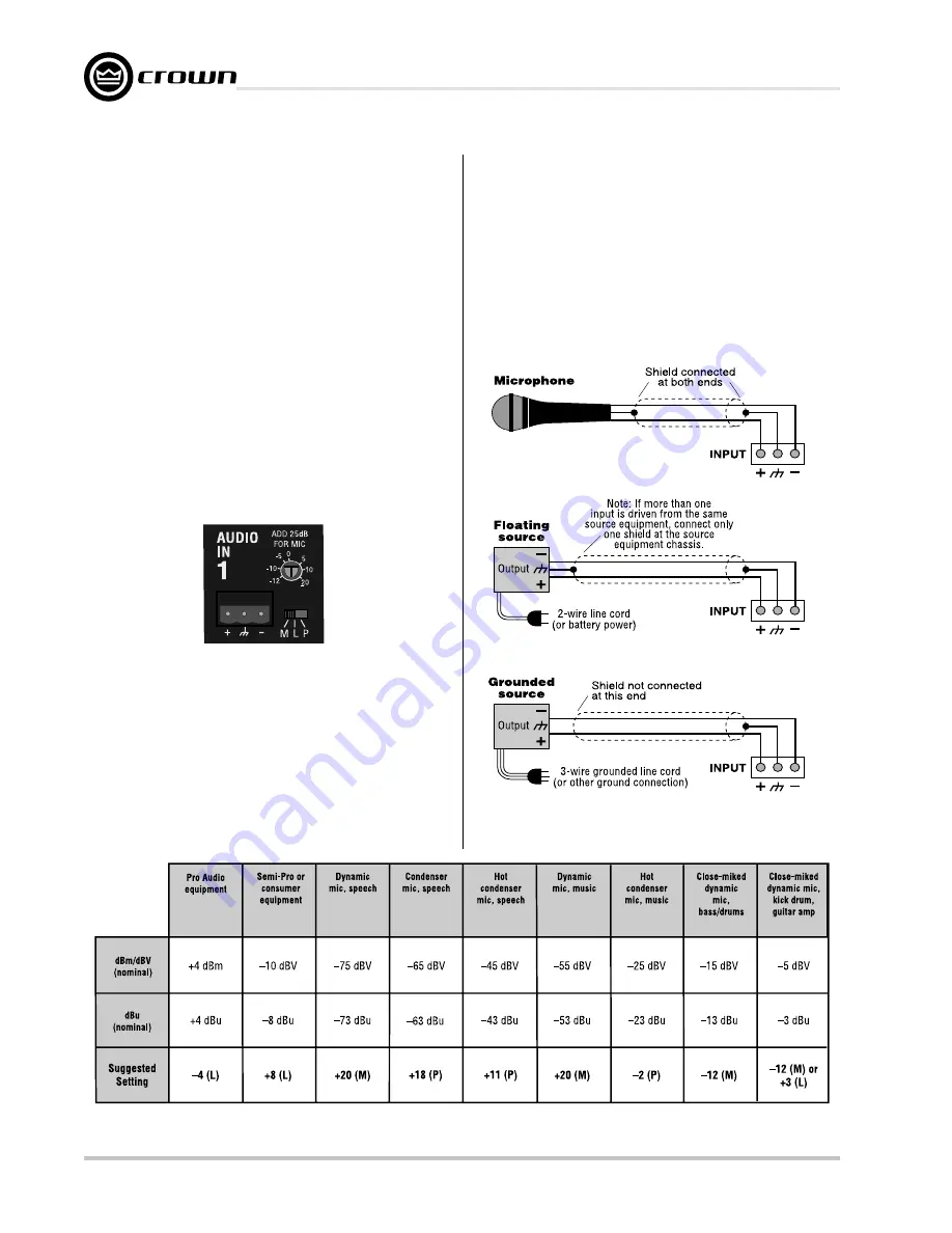
Three-terminal removable barrier block connectors are
provided for the audio inputs (see Figure 6.1). Each
input has an input selector switch. Slide it to the left (M)
for microphone signal levels up to –5 dBu (0 dBu =
0.775 volts). Select the center position (L) for line level
signals up to +20 dBu. Slide it to the right (P) to provide
24VDC to mics requiring phantom power.
will need to know, or estimate, the level of the input
source. Setting the source signal level to approximately
0 dBu will provide 20 dBu of headroom in the input
preamp. Some recommended settings are given in
Figure 6.2.
Balanced sources should be wired as shown in Figure
6.3. Notice that the shield is not connected to the
chassis ground of the source if the source is also
connected to the AC ground (that is, it has a grounded
AC plug). This prevents unwanted ground loops.
Fig. 6.2 Suggested Audio Input Gain Control Settings
Figure 6.1 An Audio Input Section
Figure 6.3 Balanced Audio Input Wiring
Each input has a screwdriver-set, calibrated gain con-
trol to compensate for different input source levels. The
slot on the control shaft points to the gain setting. The
settings are labelled for line-level input. Add 25 dB to
the scale if the inputs are switched for microphone
level signals.
Use a screwdriver to adjust the gain pot so that the
input signal level plus gain equals roughly 0 dBu. You
0 dBm = 0.775 VRMS with a 600-ohm load, 0 dBV = 1 VRMS, 0 dBu = 0.775 VRMS
Содержание IQ-USM 810
Страница 29: ...Page 29 IQ USM 810 IQ Digital Processor Digital Mixer IQ USM 810 Reference Manual...
Страница 40: ......


