Page 12
IQ-USM 810
IQ Digital Processor / Digital Mixer
IQ-USM 810
Reference Manual
3.3 Connect the Audio Wiring (Step 3)
The IQ-USM 810 has eight mic/line inputs, two main
outputs and eight AUX outputs Three-terminal remov-
able barrier block connectors are provided for the mic/
line inputs and main and AUX outputs. See Section 6.1
for information on the operation of the IQ-USM 810
inputs and outputs.
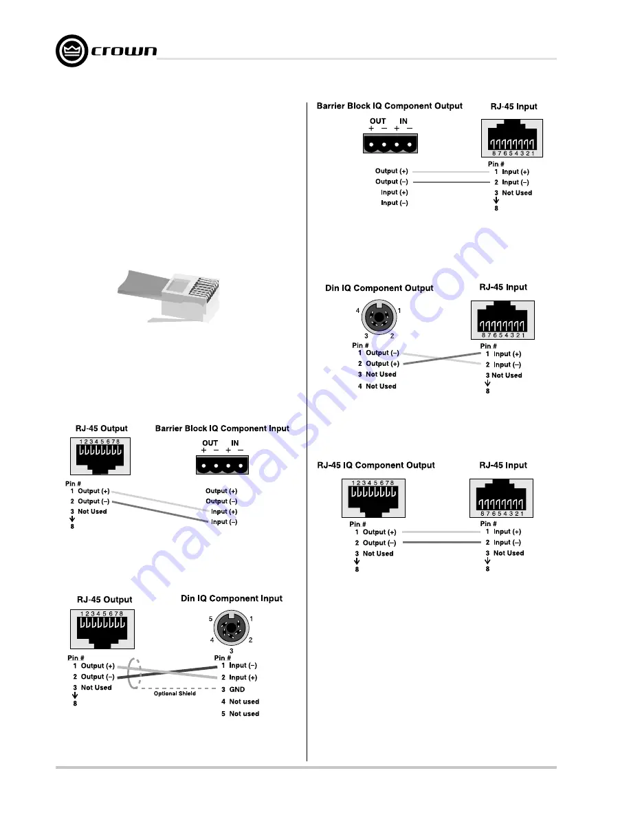
Figure 3.3 RJ-45 Plug
Figure 3.5 RJ-45 Output to Din Input
Figure 3.6 Barrier Block Output to RJ-45 Input
Figure 3.7 Din Output to RJ-45 Input
Figure 3.8 RJ-45 Output to RJ-45 Input
Figure 3.4 RJ-45 Output to Barrier Block Input
3.2.2 Connect the IQ-USM 810 to the IQ
System
via the IQ Bus
The IQ components in an IQ Bus loop are wired se-
quentially. The loop begins and ends with the IQ inter-
face. The output of one IQ component “loops” to the
input of the next and so on as shown in Figure 3.9.
Three different types of connectors are used for IQ Bus
wiring on IQ components. These include DIN connec-
tors, RJ-45 connectors, and removable barrier strip
plugs. The IQ-USM 810 uses RJ-45 connectors that
accept plugs like the one shown in Figure 3.3.
The following examples show how to connect the IQ-
USM 810 to other IQ components on the IQ Bus:
Содержание IQ-USM 810
Страница 29: ...Page 29 IQ USM 810 IQ Digital Processor Digital Mixer IQ USM 810 Reference Manual...
Страница 40: ......


