Page 17
IQ-USM 810
IQ Digital Processor / Digital Mixer
IQ-USM 810
Reference Manual
Low-Pass Crossover Filter
Description: This filter rolls off high frequencies at a rate
determined by the shape parameter. The filter is com-
monly used to feed the low-frequency portion of an
audio signal to woofers or subwoofers. It can be com-
bined with a high-pass crossover filter to create a band-
pass crossover filter for driving mid-range drivers.
Passband gain:
Sets the amount of boost or cut for the
filter. Control range is +24 dB to –24 dB in
1
/
2
-dB steps.
Frequency:
Sets the –3-dB corner frequency of the
filter. Control range is 20 Hz to 20 kHz in 1-Hz incre-
ments.
Shape:
Sets the response shape of the filter. Available
response shapes are: 1st-order Butterworth, 2nd-order
Butterworth, 3rd-order Butterworth, 4th-order
Butterworth, 2nd-order Bessel, 3rd-order Bessel, 4th-
order Bessel and 4th-order Linkwitz-Riley.
High-Pass Crossover Filter
Description: This filter rolls off low frequencies at a rate
determined by the shape parameter. The filter is com-
monly used to feed the high-frequency portion of an
audio signal to horns or tweeters. It can be combined
with a low-pass crossover filter to create a band-pass
crossover filter for driving mid-range drivers.
Passband gain:
Sets the amount of boost or cut for the
filter. Control range is +24 dB to –24 dB in
1
/
2
-dB steps.
Frequency:
Sets the –3-dB corner frequency of the
filter. Control range is 20 Hz to 20 kHz in 1-Hz incre-
ments.
Shape:
Sets the response shape of the filter. Available
response shapes are: 1st-order Butterworth, 2nd-order
Butterworth, 3rd-order Butterworth, 4th-order
Butterworth, 2nd-order Bessel, 3rd-order Bessel, 4th-
order Bessel and 4th-order Linkwitz-Riley.
Parametric Equalization Filter
Description: This filter boosts or cuts a relatively narrow
frequency band like a band-pass filter. It is commonly
used to correct specific anomalies in the response of
drivers.
Passband Gain:
Sets the amount of boost or cut for the
filter. Control range is +24 dB to –24 dB in
1
/
2
-dB steps.
Frequency:
Sets the center frequency of the filter. Con-
trol range is 20 Hz to 20 kHz in 1 Hz increments.
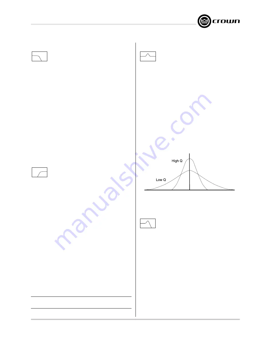
Octave Bandwidth:
Sets the width and slope, or “Q” of
the filter (see Figure 4.1). The lower the Q, the wider
the filter and the better the transient response and visa
versa. Control range is from 0.0416 (
1
/
24
octave) to 6.667
(6
2
/
3
octave) in 0.0416 (
1
/
24
-octave) increments.
CAUTION: Avoid excessive Qs.*
* High Q filters with gain greater than unity can cause unwanted ringing. This
is true for both digital and analog filters.
** The low and high-pass equalization filters can be cascaded to form unique
inter-order crossover-type filters.
Figure 4.1 Effect of Q-Factor on Filter Response
Low-Pass Equalization Filter
Description: This filter combines the functions of the
parametric equalization filter to boost or cut a relatively
narrow frequency band with a low-pass filter to roll of the
frequencies above the center frequency.**
Passband Gain:
Sets the amount of boost or cut for the
filter. Control range is +24 dB to –24 dB in
1
/
2
-dB steps.
Frequency:
Sets the center frequency of the filter. Con-
trol range is 20 Hz to 20 kHz in 1Hz increments.
Octave Bandwidth:
Sets the width and slope, or “Q” of
the filter (see Figure 4.1). The lower the Q, the wider
the filter and the better the transient response and visa
versa. Control range is from 0.0416 (
1
/
24
octave) to 6.667
(6
2
/
3
octave) in 0.0416 (
1
/
24
-octave) increments.
CAUTION: Avoid excessive Qs.*
Содержание IQ-USM 810
Страница 29: ...Page 29 IQ USM 810 IQ Digital Processor Digital Mixer IQ USM 810 Reference Manual...
Страница 40: ......


