MPR/MIB User’s Manual
Wireless Sensor Networks
Doc. # 7430-0021-06 Rev. A
Page 44
14.2.1
Physical
For other than temporary installations, the MIB600 should be installed in a ground isolated
enclosure.
14.2.2
MICA Mote Connection
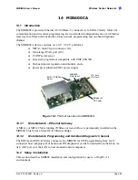
MICAz and MICA2 Motes connect to the MIB600 directly via the standard mote 51-pin
HIROSE connector at J1. Two mounting holes are provided for securing the MICA2 Mote when
installed at J1. It is recommended that these mounting points be used for longer term installations
to ensure a reliable mechanical and electrical connection to the MIB600.
14.2.3
Power
Two power supply sources are available with the MIB600
q
External 5VDC from AC wall-power adaptor
q
Power Over Ethernet
External 5VDC Power Supply
q
Connect the external 5VDC power supply to an AC 110-240V power source.
q
Place the MIB600 SW2 in the POE position
q
Connect the DC plug to J7 of the MIB600
X
NOTE:
Turn-on the MIB by placing the SW2 in the 5V position. Turn-off by placing the SW2 in the POE
position.
Power Over Ethernet / IEEE802.3af (POE).
M
WARNING!
The Mote “ground” is at POE potential (-48 V). Do not connect MIB600 to facility/building
ground when using POE.
An IEEE 802.3af compliant power supply is provided for POE equipped facilities. Ethernet
appliance power (-48 V) is supplied at pins 4/5 and 7/8 of the 10/100 Base-T RJ45 plug. Refer to
Appendix A for Base- T wiring information.
The MIB600 POE circuit contains IEEE 802.13f compliant power sequencing and classification
circuitry. Reversed and over- voltage protection is provided.
X
NOTE:
The MIB600 only supports POE over the “spare wires” 4/5 and 7/8. It does not support POE
shared on the Base-T signaling lines.
q
Connect the MIB600 to a POE-equipped LAN port.
q
Turn-On the MIB600 by placing the MIB600 SW2 in the POE position
q
Turn-Off by placing SW2 in 5V position (with External 5VDC supply
disconnected)
14.2.4
MIB600–LAN Connection
The MIB600 Serial Server connects directly to a 10 Base-T LAN as any other network device.
Straight cables are used to connect to a hub or switch. If your connection is an MIB600 to PC
you
must
use a crossed cable. Refer to Appendix A for LAN wiring information.
Содержание MIB300
Страница 1: ...MPR MIB User s Manual Rev A August 2004 Document 7430 0021 06 ...
Страница 9: ...MPR MIB User s Manual Wireless Sensor Networks Doc 7430 0021 06 Rev A Page 7 2 2 2 CC2420 Radio ...
Страница 10: ...MPR MIB User s Manual Wireless Sensor Networks Doc 7430 0021 06 Rev A Page 8 2 2 3 Battery ADC1 ...
Страница 53: ......

