MPR/MIB User’s Manual
Wireless Sensor Networks
Doc. # 7430-0021-06 Rev. A
Page 47
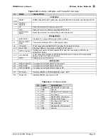
Table 14-6.
Controls, Indicators, and Connector Summary.
ID
NAME
DESCRIPTION
CONTROLS
SW1
RESET
MIB600 Manual RESET pushbutton. Resets MIB600 ISP controller and attached MOTE.
SW2
POWER
SELECT
5V
Selects External 5VDC power source at J7
POE
Selects Power Over Ethernet provided at RJ45/J10
Serial Server
Reset
Reset Serial Server. Located on Server sub module U15
CONNECTORS
J1
MOTE I/O 51
Standard 51 Position MICAx-series Mote interface
J7
External 5VDC
Input
Connects to external 5VDC +/-20% power supply
J9
JTAG-ISP
JTAG connection to MIB600 ISP Controller. For Factory Test only
J10
RJ45 / LAN
Ethernet 10Base-T connection (w/ IEEE 802.3af option)
J11
MOTE Umbilical
Umbilical connection to Mote Adapter PCB. Used for connection to MICA2 and
MICA2DOT motes.
J12
JTAG-MOTE
JTAG connection to attached MICA2/MICA2DOT Mote. Provides JTAG connectivity
between external JTAG pod and Mote.
COM1
Factory use only. Do not use
INDICATORS
D2
MOTE-YELLOW
Corresponds to attached Mote’s Yellow LED
D4
MOTE-RED
Corresponds to attached Mote’s Red LED
D7
MOTE-GREEN
Corresponds to attached Mote’s Green LED
D3
ISP Active
Indicates MIB600 in PROGRAMMING mode – RED
D5
Power OK
Indicated MIB600 input power is OK
Table 14-7.
J12 Mote JTAG
PIN
NAME
DESCRIPTION
1
TCK/ADC4 MICA2(DOT) JTAG Clock
2
GND
Ground
3
TDO
MICA2(DOT) JTAG Data Out
4
VCC
3.3V Power
5
TMS
MICA2 (DOT) JTAG Sync
6
RSTN
MICA2 (DOT) Reset
7
VCC
3.3V Power to JTAG Pod
8
N/C
Not connected
9
TDI
MICA2(DOT) JTAG Data In
10
GND
Ground
Содержание MIB300
Страница 1: ...MPR MIB User s Manual Rev A August 2004 Document 7430 0021 06 ...
Страница 9: ...MPR MIB User s Manual Wireless Sensor Networks Doc 7430 0021 06 Rev A Page 7 2 2 2 CC2420 Radio ...
Страница 10: ...MPR MIB User s Manual Wireless Sensor Networks Doc 7430 0021 06 Rev A Page 8 2 2 3 Battery ADC1 ...
Страница 53: ......

