


MPR/MIB User’s Manual
Wireless Sensor Networks
Doc. # 7430-0021-06 Rev. A
Page 38
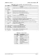
13 MIB510 S
ERIAL
I
NTERFACE
B
OARDS
X
NOTE:
The MIB510 will only work with ATMega128 processors used on the MICA2 and MICA2DOT.
It will work for older Mica units that have the ATMega128 processor but not earlier processors such as the
ATMega103.
13.1 Product Summary
The MIB510 interface board is a multi-purpose interface board used with the MICAz, MICA2,
MICA, and MICA2DOT family of products. The board is supplied with all MOTE-KITs. It
supplies power to the devices through an external power adapter option, and provides an
interface for a RS-232 Mote serial port and reprogramming port.
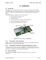
Fig 6.1
Photo of top view of an MIB510CA.
13.2 ISP
The MIB510 has an on-board in-system processor (ISP)—an Atmega16L located at U14—to
program the Motes. Code is downloaded to the ISP through the RS-232 serial port. Next the ISP
programs the code into the mote. The ISP and Mote share the same serial port. The ISP runs at a
fixed baud rate of 115.2 kbaud. The ISP continually monitors incoming serial packets for a
special multi-byte pattern. Once this pattern is detected it disables the Mote’s serial RX and TX,
then takes control of the serial port.
M
WARNING:
Some USB to DB9 serial port adapters cannot run at 115 kbaud.
The ISP processor is connected to two LEDs, a green LED labeled “SP PWR” (at D3) and a red
LED labeled “ISP” (at D5). SP PWR is used to indicate the power state of the MIB510 (see
below). If the ISP LED is on, the MIB510 has control of the serial port. It will also blink once
when the RESET (SW1) button is pushed and released.
13.3 Mote Programming Using the MIB510
Programming the Motes requires having TinyOS installed in your host PC. Instructions for
installing TinyOS can be found in Crossbow’s
Getting Started Guide
or on- line at
http://www.tinyos.net/download.html
. The commands for downloading build (compiled) code
ISP LED (red)
MICAx-series
connector
MICA2DOT connector on
bottom side
Mote JTAG connector
RS-232 Serial Port
(DB9 female)
Reset Switch (SW1)
X
NOTE:
Enable/Disable
Mote TX switch (“SW2”).
This should normally be
in the “OFF” position.
AC Wall-Power
Connector
Power OK LED
(green)
Содержание MIB300
Страница 1: ...MPR MIB User s Manual Rev A August 2004 Document 7430 0021 06 ...
Страница 9: ...MPR MIB User s Manual Wireless Sensor Networks Doc 7430 0021 06 Rev A Page 7 2 2 2 CC2420 Radio ...
Страница 10: ...MPR MIB User s Manual Wireless Sensor Networks Doc 7430 0021 06 Rev A Page 8 2 2 3 Battery ADC1 ...
Страница 53: ......


