MPR/MIB User’s Manual
Wireless Sensor Networks
Doc. # 7430-0021-06 Rev. A
Page 39
depend on the Mote platform you are programming. Instructions can also be found in the
Getting
Started Guide
.
M
WARNING:
Under Cygwin the ISP may not get control of the serial port if the Mote is continually
sending packets over the serial TX line at a high rate. If this happens, the UISP will hang. This can be
fixed by:
1. Type
Ctrl C
in the Cygwin window and try again.
2. Turn SW2 to the “ON” position. This turns on a circuit to disable the Mote’s TX line. Be sure to set
SW2 to ‘OFF’ after programming the mote if you are using the Mote as a base station (e.g., a
MICAz or MICA2 Mote programmed with
Surge_Reliable
as node “0” or with
TOSBase
).
13.4 Interfaces to MICAz, MICA2, and MICA2DOT
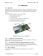
The MIB510 has connectors for both the MICA2 and MICA2DOT. See the picture below. For
the MICA2 there is another connector on the bottom side of the MIB510 for sensor boards.
MICA2DOTs with battery connectors can be mounted, also, to the bottom side of the board.
13.4.1
Reset
The “RST MOTE” push button switch resets both the ISP and Mote processors. RST resets the
ISP; after the ISP powers-up it resets the Mote’s processor.
13.4.2
JTAG
The MIB510 has a connector, J3 (“MOTE JTAG”) which connects to an Atmel JTAG pod for
in-circuit debugging. This connector will supply power to the JTAG pod; no external power
supply is required for the pod.
M
WARNING:
The MIB510 also has JTAG and ISP connectors for the ISP processor. These are for
factory use only.
13.4.3
Power
The MIB510 has an on-board regulator that will accept 5 to 7 VDC, and supply a regulated 3
VDC to the MICAz, MICA2, and MICA Motes. The MIB510 is delivered with a wall power
supply.
M
WARNING:
Applying more than 7 VDC will damage the on-board linear regulator.
There is a built- in low voltage monitor that disables reprogramming if the power supply voltage
is dangerously low. When the proper programming voltage exists the “ISP PWR” LED is on. If
the voltage goes below 2.9 V, the green “ISP PWR” LED will blink and disable the Mote from
any code downloads. If the voltage is too low to power the ISP then the “ISP PWR” LED will be
off.
M
WARNING:
When programming a MICA2 with the MIB510, turn off the battery switch. For a
MICA2DOT, remove the battery before inserting into the MIB510. The MICA2s and MICA2DOTs do not
have switching diodes to switch between external and battery power.
13.4.4
RS-232 Interface
The RS-232 interface is a standard single channel bi-directional interface with a DB9 connector
to interface to an external computer. It uses the transmit and receive lines only.
Содержание MIB300
Страница 1: ...MPR MIB User s Manual Rev A August 2004 Document 7430 0021 06 ...
Страница 9: ...MPR MIB User s Manual Wireless Sensor Networks Doc 7430 0021 06 Rev A Page 7 2 2 2 CC2420 Radio ...
Страница 10: ...MPR MIB User s Manual Wireless Sensor Networks Doc 7430 0021 06 Rev A Page 8 2 2 3 Battery ADC1 ...
Страница 53: ......


