MPR/MIB User’s Manual
Wireless Sensor Networks
Doc. # 7430-0021-06 Rev. A
Page 15
4 MPR500/MPR510/MPR520 (MICA2DOT)
4.1
Product Summary
The MICA2DOT is a Mote designed for applications where physical size is important. Like the
MICA2, these are available in three models according to the frequency of the RF transceiver: the
MPR500 (915 MHz), MPR510 (433 MHz), and MPR520 (315 MHz). The Motes use the
Chipcon CC1000 FSK-modulated radio. All models utilize a powerful ATMega128L micro-
controller and a frequency tunable radio with extended range. The MPR4
x
0 and MPR5
x
0 radios
are compatible and can communicate with each other as long as the “
x”
is the same number.
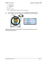
Figure 4-1.
Photos of the MICA2DOT shown next to a US quarter: a) Top-side and b) Bottom-
side. Typically the MICA2DOT has a 3 V coin-cell battery holder attached to the bottom-side,
but it has been removed to show the details.
4.2
On-board Thermistor
The MICA2DOT Mote has an on-board thermistor (Panasonic ERT-J1VR103J) which is a
surface mount component. It is on the ATMega128 side of the board at the location labeled
“RT1.” Its output is at ADC1 and is enabled by setting PW6 (PC6/A14) to “LO” and PW7
(PC7/A15) to “HI.”
The Mote’s ADC output can be converted to degrees kelvin in the 273.15 K to 323.15 K (0°C to
50 °C) range using the
Steinhart-Hart
equation, which is a widely used third-order
approximation.
3
)
(ln
ln
1
)
(
thr
thr
R
c
R
b
a
K
T
+
+
=
where:
(
)
ADC
FS
ADC
ADC
R
R
thr
−
×
=
_
1
and
a
,
b
and
c
are called the
Steinhart-Hart
parameters with the following values:
a
= 0.00130705
(a) Top-side
(b) Bottom-side
Atmel
®
ATMega128
Chipcon
®
CC1000
Содержание MIB300
Страница 1: ...MPR MIB User s Manual Rev A August 2004 Document 7430 0021 06 ...
Страница 9: ...MPR MIB User s Manual Wireless Sensor Networks Doc 7430 0021 06 Rev A Page 7 2 2 2 CC2420 Radio ...
Страница 10: ...MPR MIB User s Manual Wireless Sensor Networks Doc 7430 0021 06 Rev A Page 8 2 2 3 Battery ADC1 ...
Страница 53: ......

