background image

2330102

.f

m

Spraying boom

- 15 -


English (translated from the original language)

user manual

9

Booklet

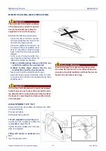
3 - Fasten stainless steel pipes 

(C)

 and guards 

(E)


(on request) to the spraying boom with the special 
supports.

NUMBER OF JETS ON EACH BOOM SECTION

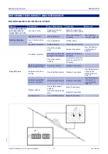
Position the nozzle holder hoses depending on the 
boom length (see diagram).

The diagram shows as well position and number of 
supports on each hose and installation 
instructions, depending on the number 
of supplies.

If the equipment is supplied disas-
sembled, the diagram is enclosed 
with the small items of the boom.

Important

For hoses with up to four jets use two 

pairs of clamps (A); for hoses with 

more than four jets use three pairs of 

clamps (B).

A

A

B

B

B

233010039-00

C

E

C

C

C

233010016-01

Содержание MHL12

Страница 1: ...CROPLANDS COM AU CROPLANDS SPRAY BOOMS OPERATORS MANUAL STOP BEFORE COMMENCING operation ENSURE you read understand this manual its contents and any additional information supplied HYDRALINK MHL 12 H...

Страница 2: ...find We welcome any feedback from you about our equipment On the back page you will find our contact details and locations where our staff can be reached during business hours After hours you can emai...

Страница 3: ...operating your sprayer 4 Terminology 4 Warranty Policy 5 SECTION 2 SAFETY 6 SECTION 3 PRODUCT IDENTIFICATION SPECIFICATION Booms Hydraulic 7 BARGAM BOOM MANUAL 1 34 SECTION 4 ASSEMBLY DRAWINGS PARTS S...

Страница 4: ...include damage to the machine itself or possible injury to the operator WARNING This warning sign shows the potential for risk or injury and highlights the need for steps to be taken to protect ones s...

Страница 5: ...for warranty matters NOTE For full conditions of warranty and warranty policy please see the Warranty Pre Delivery booklet provided with this sprayer GP WARL A 1 GP WARL A WWW CROPLANDS COM AU LINKAG...

Страница 6: ...lands Web site or for printed versions contact Croplands customer support and ask for part number GP SAFE A or later version if available WWW CROPLANDS COM AU SAFETY MANUAL OPERATORS STOP BEFORE COMME...

Страница 7: ...5 Using left right hydraulic kit option each side can be lifted independently which also automatically locks the self levelling system UNIT MHL12 Heavy duty galvanised 12m full hydraulic folding boom...

Страница 8: ...writing of the Manufacturer The Manufacturer follows a continuous improvement policy and reserves the right to change this document without notice provided that such changes do not imply risks to safe...

Страница 9: ...function hydraulic system with electric switch and control panel 10 Boom folding and unfolding 11 4 function hydraulic system with double effect solenoid valves 12 Boom folding and unfolding 13 Instal...

Страница 10: ...t the ground is uneven The equipment is divided into folding boom sections in order to adapt it to the spraying width and so as to re duce the space occupied during transfer TECHNICAL SPECIFICATIONS B...

Страница 11: ...t is necessary to keep a distance higher than the value D given in the table 12 6 5 4 12 5 6 25 5 63 15 7 5 6 8 Safety distance table Safety distance diagram Self levelling device locking device A it...

Страница 12: ...position INFORMATION ABOUT HANDLING AND INSTALLATION HANDLING INSTRUCTIONS Comply with the information provided by the manufac turer found on the equipment and in the instruction manual when carrying...

Страница 13: ...with forks or hooks having a sufficient capacity Position the lifting device as shown in the figure Avoid sudden manoeuvres Danger Warning Lifting and handling operations must be carried out by using...

Страница 14: ...of the boom already mounted on the self levelling device see Self levelling Device booklet and fasten it to the slid ing frame of the lifting device B or to the shock absorber if required INSTALLATIO...

Страница 15: ...od E by means of pins F 3 Install cable G as shown in the figure 4 Install the opposite arm by follow ing the same instructions INSTALLATION OF THE HYDRAULIC SYSTEM Proceed as follows 1 Connect the ho...

Страница 16: ...anel and is acti vated from the tractor s driver s seat The control panel must be installed in such a way that the driver can use it easily Electric switch with control panel How to use the controls 1...

Страница 17: ...om the original language user manual 9 Booklet Boom folding and unfolding The figure indicates the procedure to follow when unfolding and folding the boom Please note the two arms can be folded or unf...

Страница 18: ...l must be installed in such a way that the driver can use it easily Electric switch with control panel How to use the controls 1 Select the function by means of switches E and acti vate the selected f...

Страница 19: ...om the original language user manual 9 Booklet Boom folding and unfolding The figure indicates the procedure to follow when un folding and folding the boom Please note the two arms can be folded or un...

Страница 20: ...double effect solenoid valves 233001012 TIF CGA CONTROL BOARD A Unfolding of left arm B Unfolding of right arm C Lifting D Hydraulic tilt adjustment E Hydraulic locking M LLER CONTROL BOARD A Unfoldin...

Страница 21: ...rom the original language user manual 9 Booklet Boom folding and unfolding The figure indicates the procedure to follow when unfolding and folding the boom Please note the two arms can be folded or un...

Страница 22: ...RS IF REQUIRED AND JETS Proceed as follows 1 Install the line filters A as shown in the figure 2 Mount the jets B next to the outlet holes of the stainless steel pipes C see the Jet number diagram for...

Страница 23: ...r hoses depending on the boom length see diagram The diagram shows as well position and number of supports on each hose and installation instructions depending on the number of supplies If the equipme...

Страница 24: ...om section 500 mm pitch INSTALLATION OF WATER HOSES Proceed as follows 1 Lay the hoses down on the boom linearly see the figure 2 Leave sufficient length so as to not impede the movements at the artic...

Страница 25: ...nual 9 Booklet 4 Secure the hoses to the boom with clamps spaced out 20 cm Important Do not tighten the clamps too much so as to avoid throttling 5 Use the Teflon seal A and tighten the stainless stee...

Страница 26: ...2330102 fm 18 English translated from the original language user manual Spraying boom 9 Booklet 5 supply water connection diagram 233001024 TIFF...

Страница 27: ...age user manual 9 Booklet INSTALLATION OF REAR LIGHT KIT 1 Install the rear light kit A and fasten it with U bolts B B A A B A B A B Rear light kits for mounted units with rear reflecting panels Rear...

Страница 28: ...Booklet INSTALLATION OF THE LOCKING PISTON ON REQUEST 1 Fix plates A to locking piston B by means of screws C 2 Position locking piston B in the middle of threaded bars D and fix plates A to the supp...

Страница 29: ...the device adjust play between sur faces according to the sliding shoes wear Proceed as follows 1 Use nuts A to bring nylon pads B closer 2 If the situation does not change despite all these operation...

Страница 30: ...and align the arms by means of screws B 3 Tighten counter nuts A 4 Perform the same adjustment on the other arm 5 When the boom is folded make sure that distance X does not exceed 4 mm Important If t...

Страница 31: ...el to the ground also in sloping and or uneven areas Important Blocking device A must be used only when the equipment is moved with folded boom Locking device A must be used only during transport whil...

Страница 32: ...portation BOOM FOLDING AND UNFOLDING Boom folding on one side in order to avoid an ob stacle Boom use with only one side unfolded Prolonged stopover or machine out of use activate locking device A in...

Страница 33: ...hill first and then the one uphill Never work if just the downhill arm is open Keep the forward speed moderate max 8 10 km h to prevent the booms from swinging and to keep spraying even Important If i...

Страница 34: ...ST THE HYDRAULIC LOCKING DEVICE Proceed as follows 1 Activate the locking device 2 Make sure that buffers A press correctly on uprights B 3 If necessary loosen lock nuts C and adjust buffers A until t...

Страница 35: ...0 hours Complete equipment Check the greased parts Grease if necessary See Lubrication points diagram page 28 Check the condition and tightness of the screws Tighten and replace if necessary Check the...

Страница 36: ...M Use PERSIAN POLIGREASE 2 grease CLEANING NOZZLES Wear protective gloves for this opera tion 1 Disassemble the bayonet A and nozzle B 2 Clean the nozzle with a jet of air and a small soft bristle bru...

Страница 37: ...es etc from breaking in the event of severe temperatures 4 Disconnect the hoses from the pressure gauges 5 Grease all the components provided with a grease nipple 6 Place the equipment in a sheltered...

Страница 38: ...ures adjust the tie rods through the nut C so that the arms stop against the adjusting screws Important If the desired adjustment cannot be obtained move one or more springs from area F to G or vice v...

Страница 39: ...ews A and remove terminal joint B 2 Remove pin C and spring D 3 Insert the new spring and pin C 4 When terminal joint B is rotated by 90 in relation with the primary arm insert first screw A 5 Align t...

Страница 40: ...figure C 18 triple pack springs D 24 triple pack springs 5 Reposition the cylinder tighten screw E and nut B so that 2 threads protrude DISPOSING OF THE EQUIPMENT Important This intervention has to be...

Страница 41: ...specially ordered For further parts information refer to www croplands com au 1 BG026966 2 BG01 1047 3 GG996000192 4 GG570500008Z 5 BB502431 13 6 GG500100010Z 7 GG919800021X 8 GG500400004Z 9 GG5001000...

Страница 42: ...rdered For further parts information refer to www croplands com au 1 BG027484 2 BG027485 3 GG950200020 4 GG500100040Z 5 GG905100014Z 6 GG905400014 7 GG9071 14042Z 8 GG500500006Z 9 GG905300010 10 GG993...

Страница 43: ...yer type Items in italics or without a part number are non stocked items and may need to be specially ordered For further parts information refer to www croplands com au 1 BG027660 2 BG020197 3 BG0078...

Страница 44: ...tration purpose only refer to sprayer for actual plumbing Parts listed are indicative of the sprayer type Items in italics or without a part number are non stocked items and may need to be specially o...

Страница 45: ...tocked items and may need to be specially ordered For further parts information refer to www croplands com au 1 BG026966 2 BG01 1047 3 GG996000192 4 GG570500008Z 5 BB502431 13 6 GG500100010Z 7 GG91980...

Страница 46: ...ordered For further parts information refer to www croplands com au 1 BG027484 2 BG027485 3 GG950200020 4 GG500100040Z 5 GG905100014Z 6 GG905400014 7 GG9071 14042Z 8 GG500500006Z 9 GG905300010 10 GG99...

Страница 47: ...non stocked items and may need to be specially ordered For further parts information refer to www croplands com au 1 BG026972 2 BG01 1072 3 BG007852 4 BG01 1821 5 BG013332 6 GG9071 1 1030Z 7 BG013331...

Страница 48: ...tration purpose only refer to sprayer for actual plumbing Parts listed are indicative of the sprayer type Items in italics or without a part number are non stocked items and may need to be specially o...

Страница 49: ...il sales croplands com au website www croplands com au NEW ZEALAND Croplands Equipment Ltd PO Box 2004 Stortford Lodge Hastings 4120 Location 1422 Omahu Road Hastings 4120 New Zealand Freecall 0800 10...

Отзывы: