6
Lotem 400 / Lotem 400 Quantum Family Site Preparation Guide
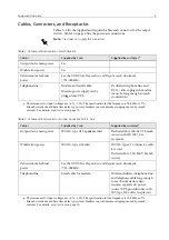
Table 4: Cables and interconnects—Japan
Table 5: Air and network connections
Cables
Supplied by Creo
Supplied by customer
a
Output device main power
(attached to either the Single
Cassette Unit or Multiple
Cassette Unit)
IEC320, type C20 appliance inlet
2.5 m (8.2 ft.) power cord with
IEC320 type C19 connector at
equipment end and L6-20P
connector at other end
L6-20R receptacle
Dedicated 20 A, 200 V branch
circuit with L6-20R receptacle
Workstation power
2.5 m (8.2 ft.) power cable with
5-15P connector
5-15R receptacle and dedicated
100V, 15A branch circuit
Debris removal cabinet
power
See the
UDRC Site Preparation and Requirements
document
(725-00089A).
Telephone line
Serial cable for modem.
Modem, dedicated telephone line,
and telephone cable long enough
to reach workstation. Also
requires separate AC power
source (UPS provided only with
5-15R receptacles).
a. The tolerances for input voltages are +6%, –10%. The specification for the frequency is 50/60Hz ±1.5%.
Branch circuits should have time delay type circuit breakers to avoid nuisance tripping caused by inrush
currents. For details, see
Other connections
Supplied by Creo
Supplied by customer
a
a. For the location of the air supply, see
on page 7. For further details, see
on page 13 and
Network connection
(for connecting to the
workflow)
Ethernet:
100 Base-T (RJ-45)
Network connection and cable
long enough to reach workstation.
FDDI: Duplex SC
Shop air supply (dedicated
branch recommended—see
0.5 in. national pipe thread (NPT)
female fitting on the device
A flexible air line, 0.75 in. ID
min., with 0.5 in. NPT fitting at
the end for connecting to the
Lotem 400 / Lotem 400 Quantum
Family.
The air line
must
be capable of
delivering 20 SCFM @ 90 psi.
Keep the air line as short as
possible and free from
restrictions. If the air line is longer
than 6.1 m (20 ft.), use a larger ID
airline.


