background image

60

SERVICIO Y AJUSTES


  ADVERTENCIA:PARA EVITAR LESIÓNES SERIAS,  ANTES DE DAR CUALQUIER SERVI-

CIO O DE HACER AJUSTES:

1.  Presione el pedal del embrague/freno completamente y aplique el freno de estacionamiento.

2.  Ponga la palanca de control de movimiento en la posición de neutro.

3.  Ponga el embrague del accesorio en la posición desenganchado (DISENGAGED).

4.  Apague el motor y bloquee el interruptor de arranque SmartSwitch.

5.  Asegúrese que las cuchillas y que todas las partes movibles se hayan detenido completamente.

6.  Desconecte el alambre de la bujía y póngalo en donde no pueda entrar en contacto con ésta.

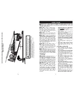
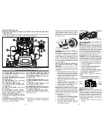
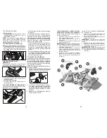
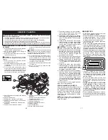
PARA DESMONTAR LA CORTADORA 

DE CÉSPED

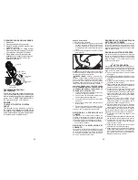
1.  Suelte el embrague poniéndolo en la posición 

“DISENGAGED” (“DESACTIVADO”).

2.  Baje la palanca elevadora de montaje a la 

posición de más abajo.

3.  Retire la barra de tensión de la correa (K) de 

la barra de sujeción (L).


CUIDADO: 

La barra de tensión de la correa 

funciona a resorte.  Sujétela con fuerza y suéltela 

despacio.
4.  Retire la correa de la cortadora de la polea 

del embrague eléctrico (M).

5.  Desconecte la pieza de unión anterior (E) de 

la cortadora – retire el resorte de contención 

y la arandela.

6.  Por uno de los lados de la cortadora, desco-

necte el brazo de suspensión de la cortadora 

(A) del chasis y la pieza de unión posterior (C) 

de la barra posterior de la cortadora (D) – retire 

los resortes de contención y las arandelas. 

7.  Por el otro lado de la cortadora, desconecte 

el brazo de suspensión y la pieza de unión 

posterior.


CUIDADO: 

Una vez que se desconecten las 

piezas de unión posteriores, la palanca elevadora 

funcionará a resorte.  Sujete con fuerza la palanca 

elevadora al cambiarla de posición.
8.  Por el lado derecho de la cortadora, desco-

necte la barra anti-balanceo (S) de la barra 

posterior derecha de la cortadora (D) – retire 

el resorte de contención y la arandela, y jale 

la cortadora hacia usted hasta que la barra 

se salga del orificio de la barra. 

9.  Haga girar el volante del tractor todo lo posible 

a la izquierda.

10. Deslice la cortadora por debajo del lado 

derecho del tractor.

A.  Brazos De Suspensión Lateral De La Cortadora 

De Césped

B.  Resorte De Retención

C. Eslabones De Levantamiento Traseros

D. Escuadra Trasera Derecha De La Cortadora 

De Césped

E.  Conjunto De Eslabones De Levantamiento 

Delanteros

F.  Escuadra De Suspensión Delantera

H. Escuadra De La Cortadora De Césped 

Delantera

I.  Escuadra Trasera Izquierda De La 

Cortadora De Césped

K.  Varilla Tensora De La Correa

L.  Escuadra De Bloqueo

M. Polea Del Embrague Del Motor

Q. Blindaje Deflector 

S. Barra Antibalanceo

W. Rueda CalIbradora Delantera

E

A

M

F

B

K

C

C

S

W

H

Q

I

D

L

17

SERVICE MINDER/HOUR METER

Service minder shows the total number of 

hours the engine has run and indicates when 

the engine or mower needs servicing. After 

every 50 hours of operation the oil can icon 

will stay on for 2 hours.  To service engine 

and mower, see the Maintenance section 

of this manual.

NOTE:

 The service minder runs when either 

the engine is running or the SmartSwitch is 

active (unlocked).

MOWING TIPS

•  DO NOT use tire chains when the mower 

hous ing is attached to tractor.

•  Mower should be properly leveled for best 

mowing performance.  See “TO LEVEL 

MOWER HOUSING” in the Service and 

Adjustments section of this manual.

•  The left hand side of mower should be 

used for trim ming.

•  Drive so that clippings are dis charged onto 

the area that has already been cut.  Have 

the cut area to the right of the tractor.  This 

will result in a more even dis tri bu tion of 

clippings and more uniform cutting.

•  When mowing large areas, start by turning 

to the right so that clippings will discharge 

away from shrubs, fences, driveways, 

etc.  After one or two rounds, mow in the 

opposite direction making left hand turns 

until finished .

• If grass is extremely tall, it should be 

mowed twice to reduce load and possible 

fire hazard from dried clip pings.  Make 

first cut relatively high; the second to the 

desired height.

•  Do not mow grass when it is wet.  Wet 

grass will plug mower and leave undesir-

able clumps.  Allow grass to dry before 

mowing.

• 

Always operate engine at full throt tle 

when mowing 

to assure better mow-

ing performance and prop er dis charge 

of material.  Reg u late ground speed by 

se lect ing a low enough gear to give the 

mower cut ting per for mance as well as the 

quality of cut desired.

• When operating attachments, se lect a 

ground speed that will suit the terrain and 

give best performance of the at tach ment 

being used.

1.  Place tractor safely on a level surface


that is clear of objects and open - with 

engine off and parking brake set.

2. Disengage transmission by placing 

freewheel control in disengaged position 

(See “TO TRANS PORT” in this section 

of manual).

3.  Sitting in the tractor seat, start en gine. 

After the engine is running, move throttle 

control to slow position. With motion 

control lever in neutral po si tion, slowly 

disengage clutch/brake pedal. 

CAUTION:

 At any time, during step 4, 

there may be movement of the drive wheels.
4.  Move motion control lever to full for ward 

position and hold for five (5) seconds. 

Move lever to full reverse position and 

hold for five (5) seconds. Repeat this 

procedure three (3) times.

5.  Move motion control lever to neutral posi-

tion. Shutoff engine and set parking brake.

6.  Engage transmission by placing free-

 wheel control in engaged position (See 

“TO TRANSPORT” in this sec tion of 

manual).

7.  Sitting in the tractor  seat, start en gine. 

After the engine is running, move throttle 

control to half (1/2) speed. With motion 

control lever in neutral position, slowly 

dis en gage clutch/brake pedal.

8.  Slowly move motion control lever forward, 

after the tractor moves ap prox i mate ly 

five (5) feet (1,5 m), slowly move motion 

control lever to reverse po si tion. After 

the tractor moves ap prox i mate ly five (5) 

feet (1,5 m) return the motion control 

lever to the neutral position. Repeat this 

pro ce dure with the motion control lever 

three (3) times.

Your transmission is now purged and now 

ready for normal operation.

Содержание 917.20401

Страница 1: ... CL TH Printed in the U S A LAWN TRACTOR 24 HP 48 Mower Electric Start Automatic Transmission Model No 917 20401 Español p 39 Operator s Manual For answers to your questions about this product call 1 888 331 4569 Craftsman Customer Help Line This product has a low emission engine which operates differently from previously built engines Before you start the engine read and understand this manual IM...

Страница 2: ...88 331 4569 or visit the web page www craftsman com warranty In all cases above if part repair or replacement is impossible the riding equipment will be replaced free of charge with the same or an equivalent model All of the above warranty coverage is void if this riding equipment is ever used while providing commercial services or if rented to another person This warranty covers ONLY defects in m...

Страница 3: ... defects or other reproductive harm Wash hands after handling SAFETY RULES I CHILDREN WARNING CHILDREN CAN BE IN JURED BY THIS EQUIPMENT The Ameri can Academy of Pediatrics recommends that children be a minimum of 12 year of agebeforeoperatingapedestriancontrolled lawn mower and a minimum of 16 years of age before operating a riding lawn mower WARNING CHILDREN CAN BE SERIOUSLY INJURED OR KILLED BY...

Страница 4: ...ing machine with grass catchers or other attachments they can affect the stabil ity of the machine Do no use on steep slopes Do not try to stabilize the machine by putting your foot on the ground Do not mow near drop offs ditches or embankments The machine could suddenly roll over if a wheel is over the edge or if the edge caves in If machine stops while going uphill disengage blades shift into re...

Страница 5: ...erno de la cuchilla 7 Acumulación de césped hojas y basura debajo de la segadora 7 Limpie la parte inferior de la cajade la segadora 8 Lacorreadeimpulsióndelasegadoraestá desgastada o desajustada 8 Cambie ajuste la correa de impulsión de la segadora 9 Las cuchillas están mal coninstaladas 9 Vuelva a instalar las cuchillas elborde afilado hacia abajo 10 Cuchillas inadecuadas en uso 10 Cambie por la...

Страница 6: ...00 professional repair specialists who have access to over 4 5 million quality parts and accessories That s thekindofprofessionalismyoucancounton to help prolong the life of your new purchase for years to come Purchase your Repair Protection Agreement today Some limitations and exclusions apply Forpricesandadditionalinformationcall 1 800 827 6655 SEARS INSTALLATION SERVICE For Sears professional i...

Страница 7: ...l es tanque de combustible o en el envase para el almacenamiento Siempre siga la proporción de mezcla que se encuentra en el envase del estabi lizador Haga funcionar el motor por lo menos 10 minutos después de agregar el estabilizador para permitir que éste llegue al carburador No vaciar la gasolina del estanque de gasolina y el carburador si se está usando estabilizador de combustible ACEITE DEL ...

Страница 8: ...location and function of controls 1 Raise attachment lift lever to its highest position 2 Release parking brake by depressing clutch brake pedal 3 Place gearshift lever in neutral position 4 Roll tractor forward off skid 5 Remove banding holding the deflector shield up against tractor Continue with the instructions that follow ADJUST SEAT 1 Sit in seat 2 Liftupadjustmentlever A andslideseat until ...

Страница 9: ... la operación normal el botón indicador de batería I no se enciende FALLAS El Botón F de SSI parpadea en rojo durante dos segundos si se introduce una contraseña incorrecta El Botón G del sistema de funcionamiento en reversa ROS parpadea cuando hay una falla en dicho sistema Consulte la sección Sistema de funcionamiento en reversa en la sección de Funcionamiento de este manual Después del primer i...

Страница 10: ...o también tiene que tener un sistema de 12 volts No use la batería de su tractor para hacer arrancar a otros vehículos PARAADJUNTARLOSCABLESDEEMPALME 1 Conecte cada extremo del cable ROJO con el terminal A B POSITIVO de cada batería preocupándose de no hacer corto circuito en el chasis 2 Conecte un extremo del cable NEGRO con el terminal C NEGATIVO de una batería completamente cargada 3 Conecte el...

Страница 11: ...ado PARA REMOVER LAS RUEDAS 1 Bloquee el eje en forma segura 2 Remueva la cubierta del eje el anillo de reten ción y las arandelas para permitir la remoción de las ruedas la rueda trasera contiene una llave cuadrada no la pierda 3 Repare la llanta y vuélvala a montar AVISO En las ruedas traseras solamente alinee las ranuras en el cubo de la rueda trasera en el eje Inserte la llave cuadrada 4 Vuelv...

Страница 12: ...f movement is controlled by the motion control lever J J F D 1 Start tractor with motion control lever in neutral position 2 Release parking brake 3 Slowly move motion control lever to desired position TO CONTINUE MOWING Return to seat Place attachment clutch switch first in DISENGAGED position and then in ENGAGED position NOTE Any attempt to place attachment clutch switch in the ENGAGED position ...

Страница 13: ...anterior de la hoja de la cuchilla quede 3 1 a 12 7 mm 1 8 a 1 2 pulgadas más abajo que la punta posterior Mantenga en la posición la tuerca de ajuste por medio de una llave inglesa y apriete bien la tuerca contra dicha tuerca de ajuste A A B B A Haga girar la tuerca hacia la derecha para subir la segadora Haga girar la tuerca hacia la izquierda para bajar la segadora Afloje la tuerca A primero B ...

Страница 14: ...witch Ignition Button F will light up and indicate the battery status as follows RED Charge necessary RED AND GREEN Charge recommended GREEN Charge not necessary Press the battery indicator button I once to stop viewing the battery status F I NOTE When the battery is too low and after the first unsuccessful start attempt the battery indicator button will blink for two 2 seconds and then stay lit u...

Страница 15: ...hould be set to primary as shown in view 3 If tractor runs out of fuel rotate valve handle to reserve 4 Drive tractor to be refueled 5 After refueling return valve to primary position Primary Primary Reserve Reserve Reserve Reserve Fuel Valve Fuel Valve F RESETTING IGNITION SYSTEM PASSCODE The SMARTSWITCH Ignition is preset at the factory with the default code 321 To reset or change the passcode t...

Страница 16: ... brake and let the brake slowly return to operating position Allowoneminutefortransmissionto warm up This can be done during the engine warm up period The attachments can also be used dur ing the engine warm up period after the transmission has been warmed up PURGE TRANSMISSION CAUTION Never engage or disengage freewheel lever while the engine is running Toensureproperoperationandperformance it is...

Страница 17: ...r see the Maintenance section of this manual NOTE The service minder runs when either the engine is running or the SmartSwitch is active unlocked MOWING TIPS DO NOT use tire chains when the mower housing is attached to tractor Mower should be properly leveled for best mowing performance See TO LEVEL MOWER HOUSING in the Service and Adjustments section of this manual The left hand side of mower sho...

Страница 18: ... del agua 6 Desde la posición del operador del tractor vuelva a arrancar el motor y ponga la palanca de aceleración en la posición Fast rápido IMPORTANTE Vuelva a comprobar la zona para asegurarse de que está despejada 7 Mueva el control del embrague del accesorio a la posición ENGANCHAR Manténgase en la posición del operador con la cubierta de corte acoplada hasta que la cubierta esté limpia 8 Mu...

Страница 19: ...esagüe empujando hacia dentro y dando vuelta en sentido de las agujas de un reloj hasta que la clavija está en la posición blo queada según lo mostrado 9 Remueva el tubo de desagüe y substituya el casquillo sobre la guarnición inferior de la válvula de desagüe 10 Vuelva a llenar el motor con aceite a través del tubo de la varilla indicadora de nivel para relleno del aceite Vacíelo lentamente No lo...

Страница 20: ...URA ANTICIPADA ANTES DEL PROXIMO CAMBIO DE ACEITE CALIDADES DE VISCOSIDAD DE SAE 20 0 30 40 80 100 30 20 0 20 30 40 F C 32 10 10 60 5W 30 SAE 30 oil_visc_chart1_s AVISO A pesar de que los aceites de multivisco sidad 5W30 10W30 etc mejoran el arranque en clima frío estos aceites de multiviscosidad van a aumentar el consumo de aceite cuando se usan en temperaturas sobre 32 F 0 C Revise el nivel del ...

Страница 21: ...r de arranque SmartSwitch SSI en verde continuo y el embrague del accesorio accionado cualquier intento del operador de cambio a reversa detiene las cuchillas de la segadora F G Con el motor en marcha el botón F del interruptor de arranque SmartSwitch SSI en verde continuo y el botón ROS G iluminado cualquier intento del operador de cambio a reversa detiene las cuchillas de la segadora 21 02463 Cl...

Страница 22: ...ery 100 hours of operation whicheveroccursfirst Sparkplug typeandgapsettingareshownin PRODUCT SPECIFICATIONS section of this manual 55 Grasa de proposito general Refiérasealaseccióndel MOTOR enMantenimiento Motor Accesorio de Grasa del Rodamiento de la Rueda Delantera Accesorio de Grasa del Arbol Accesorio de Grasa del Arbol Accesorio de Grasa del Rodamiento de la Rueda Delantera Plancha del engra...

Страница 23: ... y sujétela durante cinco 5 segundos Repita este proceso tres 3 veces 5 Mueva la palanca del control de movimiento a la posición de neutro N Apague el motor y embrague el freno de estacionamiento 6 Enganche la transmisión poniendo el control de rueda libre en la posición de conducir Vea PARA TRANSPORTAR en esta sección del manual 7 Sentado en el asiento del tractor empiece el motor Después que est...

Страница 24: ...e prolongado mantenga presionado el botón SSI durante tres segundos Esto impulsa al motor a intentar el ar ranque durante hasta diez segundos en lugar de los cinco segundos normales para dar tiempo a que el combustible entre en el motor ARRANQUE NORMAL 0 C 32 F y superior 1 Desplaceelcontroldeaceleraciónalaposición rápida 2 Sigalosprocedimientosindicadosen DESBLO QUEO DEL ARRANQUE CON SmartSwitch ...

Страница 25: ...tor 1 Presione el botón de arranque SmartSwitch SSI F una vez o sitúese en el asiento Asegúrese de que el indicador parpadea en azul 2 Presione y sostenga los botones 1 y 3 en forma simultánea durante aproximadamente tres 3 segundos hasta que el botón de SSI cambie a azul fijo 3 Use los botones numerados para ingresar la contraseña deseada La contraseña puede ser de uno a cinco dígitos de longitud...

Страница 26: ... aceite y límpielas vuelva a insertar la varilla indicadora de nivel y atornille la tapa hasta que quede apretada espere por unos cuantos segundos remuévala y lea el nivel del aceite Si es necesario agregue aceite hasta que se haya alcanzado la marca lleno FULL en la varilla indicadora de nivel No lo llene demasiado Para la operación en clima frío debe cambiar el aceite para poder arrancar más fác...

Страница 27: ... ac cionado No siegue en reversa a menos que sea absolutamente necesario USO DEL SISTEMA DE FUNCIONAMIENTO EN REVERSA Úselo solo si está seguro de que no accederán niños ni otras personas a la zona de corte del césped 1 Con el motor en funcionamiento pise el pedal de freno a fondo 2 Presione el botón ROS G y asegúrese de que esté encendido G 3 Siempre mire hacia abajo y hacia atrás antes y cuando ...

Страница 28: ... correctamente si el operador no está situado en el asiento F D A PARA AJUSTAR LA ALTURA DE CORTE DE LA SEGADORA La posición de la palanca elevadora A determina a qué altura se cortará el césped Coloque la palanca elevadora en la ranura de la altura deseada La gama de la altura de corte es de aproximada mente 25 4 to 101 6 mm 1 a 4 pulgadas Las alturas se miden desde el suelo a la punta de la cuch...

Страница 29: ... manual PARA DEJAR DE SEGAR Situado en el asiento en la posición de trabajo pise el pedal del freno y accione el freno de estacionamiento Después de accionar el freno de estacionamiento cualquier intento del operador de abandonar el asiento detendrá las cuchillas de la cortadora de césped El motor seguirá funcionando durante unos cinco minutos antes de apagarse Esto permite al operador dejar del a...

Страница 30: ...d REPLACING BATTERY WARNING Donotshortbatteryterminals by allowing a wrench or any other object to contact both terminals at the same time Before connecting battery remove metal bracelets wristwatch bands rings etc Positive terminal must be connected first to preventsparkingfromaccidentalgrounding 1 Lift seat pan to raised position NOTE Onrearwheelsonly aligngroovesin rear wheel hub and axle Inser...

Страница 31: ...nd keps nut as shown Tighten securely Slide terminal cover over terminal 5 Connect BLACK grounding cable to negative terminal with remaining hex bolt and keps nut Tighten securely Seat pan TO REPLACE HEADLIGHT BULB 1 Raise hood 2 Remove bulb holder from the hole in the backside of the grill 3 Replace bulb in holder and install bulb holder securely back into the hole in the backside of the grill 4 ...

Страница 32: ...adecuado alrededor de las poleas y dentro de todos los fijadores de las correas Revise el alambrado Fíjese que todas las conexiones todavía estén seguras y que los alambres estén sujetos en forma adecuada Al mismo tiempo que aprende a como usar su tractor preste atención extra a los puntos de importancia que se presentan a continuación El aceite del motor tiene que llegar al nivel adecuado Elestan...

Страница 33: ...or are empty Never use engine or carburetor cleaner products in the fuel tank or permanent damage may occur Use fresh fuel next season NOTE Fuel stabilizer is an acceptable al ternative in minimizing the formation of fuel gum deposits during storage Add stabilizer to gasoline in fuel tank or storage container Alwaysfollowthemixratiofoundonstabilizer container Run engine at least 10 minutes afterad...

Страница 34: ...grama regular de mantenimiento cuidado y uso de su tractor Siga las instrucciones descritas en las sec ciones Mantenimiento y Almacenamiento de este manual Utilice prendas de seguridad adecuadas al manejar la máquina incluidos como mínimo calzado de seguridad gafas protectoras y pro tección auditiva No utilice pantalones cortos y o calzado abierto cuando corte la hierba Informe siempre a alguien d...

Страница 35: ...ión Verifique los componentes de la trampa para césped y la canaleta de descarga con frecuen cia y sustituya con repuestos recomendados por el fabricante cuando sea necesario Las cuchillas del cortacésped son afiladas Envolver la cuchilla ponerse guantes y poner la máxima atención cuando se hacen opera ciones en ellas Controlar el funcionamiento del freno frecuent emente Ajustar y hacer las operac...

Страница 36: ...radores tendrían que evaluar su habilidad de hacer funcionar el cortacésped de modo lo bastante seguro para proteger a sí mismos y a otras personas de heridas graves Seguir las recomendaciones del fabricante para los pesos y contrapesos de las ruedas Mantener la máquina libre de hierba hojas u otros escombros que pueden tocar el tubo de escape partes del motor calientes y quemarse No permitir que ...

Страница 37: ...y abajo para ver si hay niños pequeños Nunca llevar niños incluso si hay las cuchillas apagadas Podrían caer y herirse seriamente o interferir con el funcionamiento seguro de la máquina los niños que se han llevado prec edentemente pueden aparecer de pronto en el área de corte por otro paseo y ser atropellados o tumbados por la máquina Nunca dejar que los niños manipulen la máquina Tener el máximo...

Страница 38: ...inal después del décimo año a partir de la fecha de compra el eje delantero de hierro colado si está instalado de este equipo tractor está garantizado ante cualquier defecto de material o mano de obra Contra la presentación del comprobante de compra se suministrará un eje delantero de hierro colado sin cargo alguno SERVICIO DE GARANTÍA Para conocer los detalles de la cobertura de garantía para obt...

Отзывы: