


page-
18
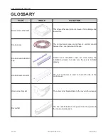
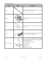
OASIS COVER
INSTALLATION
PROCEDURE
This section shows the procedure on how to install
your new cover on your spa.
It requires two people for certain steps.
Wear the necessary PPE such as protective
glasses, boots and gloves.
CAUTION
The cover should be installed by a certified Covana
installer. Having the cover installed by someone
who is not certified will void the warranty.
Ask your local Covana dealer for information on
certified installers.
TOOLS REQUIRED
l
Scissors or a utility knife
l
Robertson screwdriver
l
Slotted screwdriver
l
Phillips screwdriver
l
Hammer
l
3/8" (10 mm) socket wrench and spanner
l
7/16" (11 mm) socket wrench and spanner
l
1/2" (13 mm) socket wrench and spanner
l
5/32" (4 mm) Drill bit (supplied)
l
7/32" (5.5 mm) Allen key
l
25' (7.62 m) measuring tape
l
Rubber mallet
l
SAE or metric Socket kit
l
48" (122 cm) level
l
Step ladder
l
J-Roller with rubber roller
PREPARATION FOR THE
INSTALLATION
To ensure safe use of the cover, it must be installed
on a properly prepared surface. It is important to
adequately prepare the foundation and carefully read
the following recommendations.
SPA LOCATION CONSIDERATIONS
Make sure the future cover location is not subject to
the water downpours or debris falling.
Make sure the base of the cover is not in a flood
zone. Any damage caused by flooding or water
accumulation will not be covered by the warranty.
Make sure there are no obstacles, such as branches
or electrical power lines, in the operating area of the
cover.
Refer to the Technical Specifications section for
cover dimensions
Make sure there is safe access to the spa, free of
obstacles or debris.
All the base components of the cover must be
supported by the foundation.
Do not converge or directly reflect sunlight on the
cover.
This
could
cause
permanent
damage
(Example: reflection from a window).
Make sure the cover is installed on a clean surface
free of any vegetation, such as grass, branches or
roots, or mineral contaminants, such as rocks, dust
or sand.
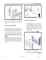
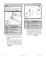
The key switch must be permanently mounted and
located 5 ft (1.5 m) away from the spa and 5 ft (1.5
m) above the deck or ground level see
. This
ensures the user has a clear view of the cover when
operating it. Furthermore, the key switch terminal
should be located in a location where no water
downpour or debris could fall on it.
DANGER
Failure to properly install the key switch according
to these instructions could result in injury or even
death.
241146
OWNER'S MANUAL
REVISION 1
Содержание OASIS COVER
Страница 1: ......
Страница 2: ......
Страница 54: ......
Страница 58: ...page 56 OASIS COVER WIRING DIAGRAM NORTH AMERICA 60 HZ 120 VAC OPERATOR 241146 OWNER S MANUAL REVISION 1...
Страница 59: ...OASIS COVER page 57 241146 OWNER S MANUAL REVISION 1...
Страница 60: ...page 58 OASIS COVER WIRING DIAGRAM NORTH AMERICA LIGHTS 60 HZ 120 VAC OPERATOR 241146 OWNER S MANUAL REVISION 1...
Страница 61: ...OASIS COVER page 59 241146 OWNER S MANUAL REVISION 1...
Страница 62: ...page 60 OASIS COVER WIRING DIAGRAM EUROPE 50 HZ 230 VAC OPERATOR 241146 OWNER S MANUAL REVISION 1...
Страница 63: ...OASIS COVER page 61 241146 OWNER S MANUAL REVISION 1...
Страница 64: ...page 62 OASIS COVER WIRING DIAGRAM EUROPE LIGHTS 50 HZ 230 VAC OPERATOR 241146 OWNER S MANUAL REVISION 1...
Страница 65: ...OASIS COVER page 63 241146 OWNER S MANUAL REVISION 1...
Страница 71: ...OASIS COVER page 69 TECHNICAL SPECIFICATIONS COVANA COVER FRONT VIEW 241146 OWNER S MANUAL REVISION 1...