


OASIS COVER page-
9
DANGER
l
Disconnect or turn off and secure all power
supplies before starting any intervention on the
cover.
l
A circuit breaker needs to be incorporated into
the fixed wiring at the time of installation. This
circuit breaker must be accessible to the user or
service technician to turn the power off for future
maintenance or repair.
l
Only a certified electrical contractor may
perform any electrical maintenance on the
cover.
The wiring must
comply
with all
applicable local electrical regulations.
l
The operator must be connected to a circuit that
is protected by a dedicated ground fault circuit
interrupter
(GFCI)
that
complies
with
all
applicable local electrical codes and regulations.
l
Install the cover in such a way that drainage
directs water away from the electrical and the
mechanical components at the base.
l
Do not connect any auxiliary components to the
electrical system of the cover unless they have
been approved by Covana.
l
Replace electrical components with original
components provided or approved by Covana.
Ask your dealer for replacement parts.
l
To reduce the risk of electrical shock, replace a
damaged electrical cord immediately. Failure to
do so may result in death or serious personal
injury due to electrocution.
l
Do not bury the electrical wires into the ground
unless using a direct-burial underground cable.
Not respecting this precaution may result in
death,
or serious
personal injury
due to
electrocution.
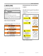
ELECTRICAL WARNING
WARNING
l
To reduce the risk of electrical shocks, the
green-colored terminal (or the terminal marked
“g,” “gr,” “ground,” “grounding” or with a
symbol) that is located inside the supply
terminal box or compartment must be connected
to the grounding connection provided in the
electric supply service panel with a continuous
copper wire equivalent in size to the circuit
conductors supplying the equipment.
l
Two lugs marked “bonding lugs” are provided on
the external surface or on the inside of the
supply terminal box or compartment. To reduce
the risk of electric shock, connect the local
common bonding grid in the area of the cover.
Use terminals with an insulated or bare copper
conductor not smaller than No. 6 AWG (4.11
mm / 13.30mm
2
).
l
All field- installed metal components, such as
rails, ladders, drains or other similar hardware,
within 10 ft (3 m) of the spa must be bonded to
the equipment grounding bus with copper
conductors not smaller than No. 6 AWG (4.11
mm / 13.30mm
2
). (NEC art. 680).
MODIFICATIONS TO THE COVER
WARNING
l
Any modifications to the cover, such as
mechanical, electrical or aesthetic, may cause
the cover to operate in an unwanted or
dangerous
way.
Furthermore,
these
modifications are not permitted and might void
the warranty and certification.
l
The cover has been designed, tested and
certified for the only purpose of covering and
securing a spa. Any installation that differs
partly or entirely from this purpose will void the
warranty and certification.
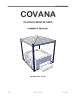
241146
OWNER'S MANUAL
REVISION 1
Содержание OASIS COVER
Страница 1: ......
Страница 2: ......
Страница 54: ......
Страница 58: ...page 56 OASIS COVER WIRING DIAGRAM NORTH AMERICA 60 HZ 120 VAC OPERATOR 241146 OWNER S MANUAL REVISION 1...
Страница 59: ...OASIS COVER page 57 241146 OWNER S MANUAL REVISION 1...
Страница 60: ...page 58 OASIS COVER WIRING DIAGRAM NORTH AMERICA LIGHTS 60 HZ 120 VAC OPERATOR 241146 OWNER S MANUAL REVISION 1...
Страница 61: ...OASIS COVER page 59 241146 OWNER S MANUAL REVISION 1...
Страница 62: ...page 60 OASIS COVER WIRING DIAGRAM EUROPE 50 HZ 230 VAC OPERATOR 241146 OWNER S MANUAL REVISION 1...
Страница 63: ...OASIS COVER page 61 241146 OWNER S MANUAL REVISION 1...
Страница 64: ...page 62 OASIS COVER WIRING DIAGRAM EUROPE LIGHTS 50 HZ 230 VAC OPERATOR 241146 OWNER S MANUAL REVISION 1...
Страница 65: ...OASIS COVER page 63 241146 OWNER S MANUAL REVISION 1...
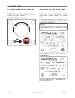
Страница 71: ...OASIS COVER page 69 TECHNICAL SPECIFICATIONS COVANA COVER FRONT VIEW 241146 OWNER S MANUAL REVISION 1...