■
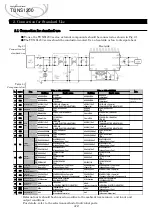
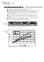
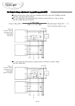
Parallel operation is available by connecting the units as shown in Fig 5.1.
■
Input capacitor C11, boost voltage circuit capacitor (Cbc, C20, C30) and Inrush current
limiting resistor TFR1 cannot be used together. Please wire for each power supply .
■
Total current should not exceed the value calculated by the following equation, and total
number of unit should be no more than 9 pieces.
(Output current at parallel operation) = (the rated current per unit)× (number of unit) ×0.9
■
Connect the sensing line and the power line by one point after connecting each power
supply's sensing pin(+S,-S). Please do not connect the sensing from the individual power
supply as it may cause unstable operation.
■
Please make sure that the wiring impedance of a load from each power supply become even.
■
Output voltage and constant current can be adjusted in parallel operation.
(Refer to item 5.2, 5.3)
■
When the input voltage is applied with remaining the voltage at boost capacitor Cbc, startup
time would be different for each paralleled module. If all paralleled modules need to startup
at the same time, remote control function shall be used.
■
If the output current is less than 2% of the rated current, the output voltage ripple will be
large. Therefore, it is recommended to use it with 2% load or more.
Fig5.1
Wiring for parallel
operation
5.1 Wiring for parallel operation
A-11
Applications Manual
TUNS1200
2.1 Pin configuration
5. Parallel operation
Noise
Filter
Noise
Filter
Noise
Filter
Sensing point
FG
AC1
AC2
+VOUT
-VOUT
+BC
-BC
FG
Cbc
+
C30
VTRM
+S
TFR1
R
C20
Cy
AC1
F11
C11
+
CB
-S
VR1
Co
FG
AC1
AC2
+VOUT
-VOUT
+BC
-BC
FG
Cbc
+
C30
VTRM
+S
TFR1
R
C20
Cy
AC1
F11
C11
+
CB
-S
Co
FG
AC1
AC2
+VOUT
-VOUT
+BC
-BC
FG
Cbc
+
C30
VTRM
+S
TFR1
R
C20
Cy
AC1
F11
C11
+
CB
-S
Co
●
●
●
AC
INPUT
Load

