background image

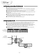
In order to smooth boost voltage, connect Cbc bBC and -BC.

Recommended capacitance of Cbc is shown in Table 2.4.

If the capacity is not within the allowable external capacity, the module may be damaged.

When operated below 0ºC, operation may become unstable as boost ripple voltage

increases due to ESR characteristics. Choose a capacitor which has higher capacitance

than recommended.

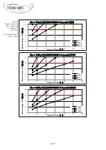
Select a capacitor so that the ripple voltage of the boost voltage is 30 Vp-p or below.

If the ripple voltage of the boost voltage increases, the ripple current rating of the

smoothing capacitor may be exceeded. Check the maximum allowable ripple current of

the capacitor.

The ripple current changes with PCB patterns, external parts, ambient temperature, etc.

Check the actual ripple current value flowing through Cbc. 

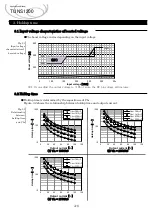
The boost voltage varies depending on the input voltage. (See item 3.1)

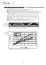
Table 2.4

Recommended

capacitance

Cbc

※ 

Refer to item 3 and 4 for selection method of Cbc.

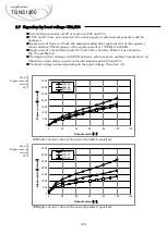
Fig.2.4

Ripple current

values

Cbc

Ripple current value is the sum of parallel capacitors.

2.6 Smoothing capacitor for boost voltage: Cbc

780u

F ~ 

3,300uF

780u

F ~ 

2,200uF

A-5

470uF×3 parallel

85 

305VAC

DC500V

以上

85 

264VAC

DC420V

以上

470uF×3 parallel

Allowable

capacitance range

Rated voltage

Input voltage

range

Recommended

capacitor

Applications Manual 

TUNS1200

0

1000

2000

3000

4000

5000

6000

7000

0

20

40

60

80

100

120

Ripp

le

 c

urren

t

m

A

rms

Output current 

%

100VAC
200VAC
277VAC

Содержание TUNS1200F Series

Страница 1: ...2021 11 22 Rev 1 1E Application manual TUNS1200F...

Страница 2: ...tion CC N 1 redundant operation Remote control 6 Other functions Power good 7 Mounting method Mounting method 8 Board layout Consideration for board layout Reference PCB layout 9 Thermal Design Therma...

Страница 3: ...e ON OFF Alarm RC1 PG FG No Function AC input External resistor for inrush current protection BC output BC output DC output Pin Connection AC1 Remote ON OFF ground Alarm ground Adjustment of output cu...

Страница 4: ...V 2200uF ELXZ250ELL222 Nippon Chemi Con DC25V 2200uF ELXZ250ELL222 Nippon Chemi Con F28 DC50V 1000uF ELXZ500ELL102 Nippon Chemi Con DC50V 1000uF ELXZ500ELL102 Nippon Chemi Con F48 DC63V 470uF ELXZ630E...

Страница 5: ...ple current Ripple current includes low frequency component input frequency and high frequency component 100kHz Ripple current values flowing into C11 as listed in Table 2 1 are shown in Fig 2 2 The r...

Страница 6: ...VOUT and VOUT pins for stable operation of the power supply Recommended capacitance of Co is shown in Table 2 3 Use low impedance electrolytic capacitors with excellent temperature characteristics Wh...

Страница 7: ...imum allowable ripple current of the capacitor The ripple current changes with PCB patterns external parts ambient temperature etc Check the actual ripple current value flowing through Cbc The boost v...

Страница 8: ...xternal parts ambient temperature etc Check the actual ripple current values flowing through C20 and C30 The boost voltage varies depending on the input voltage See item 3 1 Fig 2 5 Ripple current val...

Страница 9: ...ired surge capacity Required surge capacity can be calculated using the following formula Please contact to the component manufacturer regarding the surge current withstanding capability I2t Current s...

Страница 10: ...put voltage characteristics of boosted voltage 3 2 Holdup time A 8 Applications Manual TUNS1200 300 350 400 450 50 100 150 200 250 300 350 Boost voltage V Input voltage VAC 1 365V 395V 430V 2 1 Pin co...

Страница 11: ...ient temperature AC200V Withstand voltage of Cbc 450V 4 1 Ripple voltage of boost voltage A 9 Applications Manual TUNS1200 0 10 20 30 40 0 20 40 60 80 100 120 Ripple voltage of BC Vp p Output current...

Страница 12: ...120 Ripple voltage of BC Vp p Output current 20 30 35 40 Cbc 780 F_ELXS501VSN391 2 parallel MIN 0 10 20 30 40 0 20 40 60 80 100 120 Ripple voltage of BC Vp p Output current 20 30 35 40 Cbc 1410 F_ELX...

Страница 13: ...even Output voltage and constant current can be adjusted in parallel operation Refer to item 5 2 5 3 When the input voltage is applied with remaining the voltage at boost capacitor Cbc startup time w...

Страница 14: ...adjustable See formula N Parallel number of unit Fig 5 2 Output voltage adjustment by external resistor By connecting the external power supply as shown in Fig 5 3 output voltage becomes adjustable Fi...

Страница 15: ...hown in Fig 5 4 constant current becomes adjustable See formula Fig 5 4 Constant current adjustment by external resistor By connecting the external power supply as shown in Fig 5 5 constant current be...

Страница 16: ...eration The remote sensing function cannot be used in N 1 redundant operation At the load end the voltage drops due to the forward voltage Vf of the diode When the output voltage is adjusted by the vo...

Страница 17: ...d Remote control wiring example When determining Vrc and Rrc the current I_RC1 flowing through each remote control circuit must satisfy the following formulas 2 and 3 Current N I_RC1 for parallel conn...

Страница 18: ...put voltage 1 V1 60 of the set output voltage 2 V2 20 of the rated output voltage 6 1 Power Good A 16 Applications Manual TUNS1200 AC Input voltage Output voltage Remote ON OFF ACin RC RC RC RC ON OFF...

Страница 19: ...e distribution of the aluminum base plate varies depending on the model and input output conditions It is recommended to use the side_B as the reference because the temperature of the side_B varies li...

Страница 20: ...mended to ensure the following Primary circuit Secondary circuit 8mm or more Primary circuit FG 5mm or more Secondary circuit FG 1 6mm or more Primary circuit Primary circuit 3mm or more AC terminal l...

Страница 21: ...e Surface Mount There are notes for printed circuit board design at recommended circuit in this applications manual Please see below Fig 8 3 Recommended external circuit Input fuse F11 F12 Y Capacitor...

Страница 22: ...depends on the place of the FG connection Recommend connecting Y capacitor to the FG terminal of the power supply as close as possible Please evaluate before use Huge ripple current flows into the cap...

Страница 23: ...the power supply is not connected properly malfunction or failure could happen Expose the solder mask around the hole of the FG connection on the PWB to connect FG terminals by screws Output capacito...

Страница 24: ...ircuit Primary circuit AC input line Wiring to BC terminal 8 2 Reference PCB layout A 22 FG Secondary circuit a Example of the pattern and components layout Top layer b Example of the pattern and comp...

Страница 25: ...heat dissipation environment Please measure the temperature of the actual equipment eventually Fig 9 1 Convection cooling Heatsink example Fig 9 2 Environment 9 1 Thermal Design 9 2 Examples of Conve...

Страница 26: ...e measure the leeward side of the baseplate edge Fig 9 4 Forced air cooling Heat sink example Fig 9 5 Environment A 24 9 3 Examples of Forced air cooling Applications Manual TUNS1200 0 200 400 600 800...

Страница 27: ...200 400 600 800 1000 1200 1400 0 20 40 60 80 100 Output power W Ambient temperature 1 0m s 2 0m s 0 200 400 600 800 1000 1200 1400 0 20 40 60 80 100 Output power W Ambient temperature 1 0m s 2 0m s 20...

Страница 28: ...Revision history A 26 19 20 15 16 17 18 13 14 11 12 9 10 7 8 5 6 3 4 1 2021 11 22 1 1E A 23 A 25 9 Thermal Design Addition 2 No date Rev page content Applications Manual TUNS1200...

Отзывы: