


■
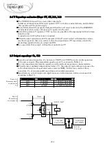
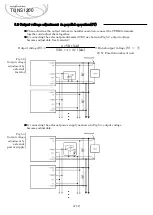
When implementing the power supply to the printed circuit board, please fix the power
supply to the printed circuit board by screw before the soldering.
If it is screwed to the substrate after soldering, there is a possibility of failure by adding
mechanical stress to the soldering point and the internal connections of power supply.
Fig.7.1
Mounting method
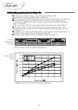
■
Please measure the temperature on the aluminum base plate edge side when you cannot
measure the temperature of the center part of the aluminum base plate. In this case,
please take 5deg to 10deg temperature margin from the derating characteristics.
■
Use a heat sink that larger than the power supply and has a large thickness so that the
aluminum base plate can be cooled uniformly.
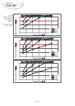
■
The temperature distribution of the aluminum base plate varies depending on the model
and input/output conditions. It is recommended to use the side_B as the reference
because the temperature of the side_B varies little depending on the operating conditions.
Fig.7.2
Effect of heat
sink thickness
(reference)
※
TUNS1200F28 at 100VAC and rated load
7.1 Mounting method
A-17
Applications Manual
TUNS1200
2.1 Pin configuration
7. Mounting method
0
1
2
3
4
5
6
7
8
9
10
0
5
10
15
20
25
⊿
T
(T
c
-
Ts
)
[
℃
]
t : Heatsink thickness
[
mm
]
side_A
side_B
side_C
side_D
Heatsink
Silicone grease
(Momentive YG6260)
External components
TUNS1200F
Printed Board
(FR-4 t=1.6mm)
<Center part of the aluminum base plate.>
(Derating curve temperature)
<Aluminum base plate edge side.>
(In
p
u
t)
(o
u
tp
u
t)
Ts : side_A
Ts : side_C
Ts : side_B
Ts : side_D
Tc : center
t
(mm)
Heat sink
Heat sink
retention screws
Silicone grease
/ Heat dissipation sheet
Power supply
Power supply
retention screws
Power supply
soldering
printed circuit board
①
②