■
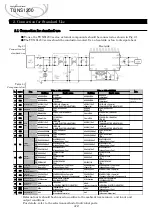
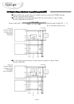
When using remote control in parallel operation, control the remote control terminals of
the power supplies in parallel at the same time, as shown in Fig.5.8 and 5.9.
Fig.5.8.
Ex.1
)
When the power output terminal and the remote control circuit are not isolated
Remote control
wiring example
※
In the case of this connection example, the control current (
I_RC1
) flows up to 9.7mA.
Current (
N×I_RC1
) for parallel connection (N) flows to the control switch.
Control current
(
I_RC1
)
= 9.7mA
Fig.5.9.
Ex.2) When the power output terminal and the remote control circuit are isolated
Remote control
wiring example
※
When determining Vrc and Rrc, the current (I_RC1) flowing through each remote
control circuit must satisfy the following formulas (2) and (3).
Current (
N×I_RC1
) for parallel connection (N) flows to the control switch.
Vrc
:
External power supply voltage
:
Vf_MIN = 0.9V
:
Vf_MAX = 1.4V
:
I_RC1current limiting resistor
5.5 Remote control
2 mA
・・・③
Rrc
≧
・・・①
A-15
12 mA
・・・②
Vf(PC1)
( Vrc - Vf_MIN )
(Rrc + 150 )
≦
( Vrc - Vf_MAX )
(Rrc + 150 )
=
Control current
(
I_RC1
)
Control current
(
I_RC1
)
=
Applications Manual
TUNS1200
RC1
RC2
-S
●
●
●
POWER
ON
OFF
AUX
1.1k
Ω
150
Ω
12typ
PC1
I_RC1
N
×
I_RC1
AUX
RC1
RC2
-S
1.1k
Ω
150
Ω
12typ
PC1
I_RC1
AUX
RC1
RC2
-S
1.1k
Ω
150
Ω
12typ
PC1
I_RC1
Control
Switch
RC1
RC2
150
Ω
PC1
I_RC1
RC1
RC2
150
Ω
PC1
I_RC1
●
●
●
RC1
RC2
150
Ω
PC1
I_RC1
Rrc
Rrc
Rrc
Vrc
POWER
ON
OFF
N
×
I_RC1
Control
Switch


