Cornwell Tools MIG 250MGS Скачать руководство пользователя страница 18

Page      of 28 

18 

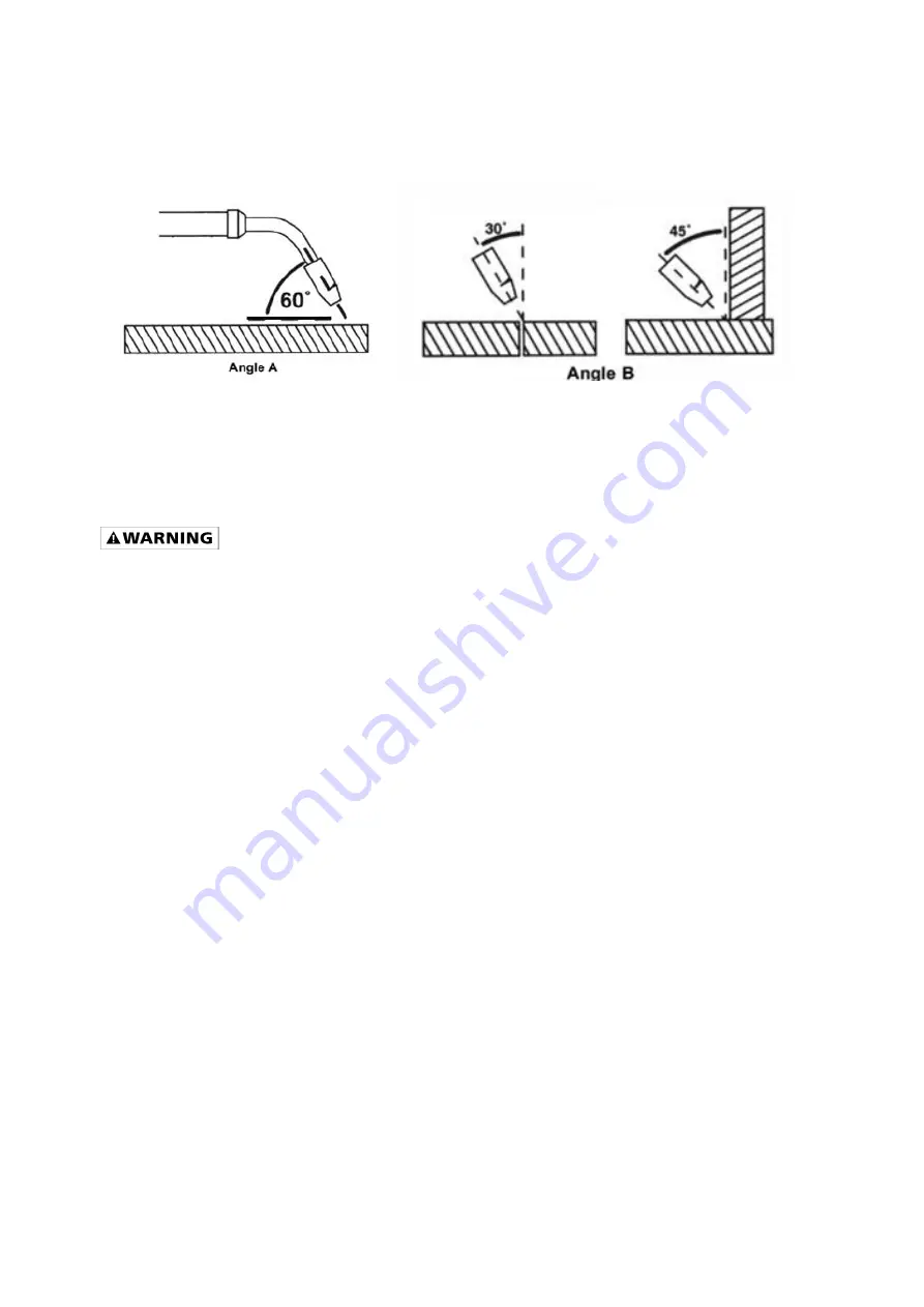
5.1.  Angle  a  can  be  varied,  but  in  most  cases  the optimum  angle  will  be  60  degrees,  the  point  at 

which the torch angle is parallel to the work piece. If angle A is increased, penetration will increase. 

If angle A is decreased, penetration will decrease also. 

5.2. Angle B can be varied for two reasons: to improve the availability to see the arc in relation to 

the weld puddle and to direct the force of the arc. 


6.  DISTANCE  FROM  THE  WORK  PIECE  -  If  the  nozzle  is  held  off  the  work  piece,  the  distance 

between the nozzle and the work piece should be kept constant and should not exceed 1/4 inch or 

the arc may begin sputtering, signaling a loss in welding performance. 

7. TUNING IN THE WIRE SPEED - This is one of the most important parts of wire welder operation 

and must be done before starting each welding job or whenever the voltage setting or wire diameter 

is changed. 


EXPOSURE  TO  A  WELDING  ARC  IS  EXTREMELY  HARMFUL  TO  THE  EYES  AND  SKIN! 

Prolonged exposure to the welding arc can cause blindness and burns. Never strike an arc 

or  begin  welding  until  you  are  adequately  protected.  Wear  flame-proof  welding  gloves,  a 

heavy long sleeved shirt, trousers without cuffs, high topped shoes, and an ANSI approved 

welding helmet. 

7.1  Connect  the  Ground  Clamp  to  a  scrap  piece  of  the  same  type  of  material  which  you  will  be 

welding. It should be equal to or greater than the thickness of the actual work piece, and free of oil, 

paint, rust, etc. 

7.2  Select a heat setting. 

7.3   Hold the torch in one hand. Hold the wire just off the work piece. (See HOLDING THE TORCH 

section if you are uncertain of the angle at which you will be welding). 

7.4   Set  the  wire  feed  speed based  on  the  thickness of material  and  the  set-up chart  on  the  back 

side of the wire feeder door. 

7.5  Lower your welding helmet and pull the trigger on the torch and let the wire feed into the work 

piece to start an arc, then begin to drag the torch toward you.   

7.6  LISTEN!  If  the  arc  is  sputtering,  increase  the  wire  speed  slightly  and  try  again.  Continue 

increasing the wire speed adjustment until you achieve a smooth buzzing sound. If the wire seems 

to  "pound"  into  the  work  piece,  decrease  wire  speed  slightly  and  try  again.  Use  the  wire  speed 

control  to  slightly  increase  or  decrease  the  heat  and  penetration  for  a  given  voltage  setting  by 

increasing or decreasing the wire speed slightly. Repeat this tune-in procedure if you select a new 

voltage setting, a different wire diameter, or a different roll of wire. 


Содержание MIG 250MGS

Страница 1: ...MANUAL 2 2016 WARNING Read carefully and understand all ASSEMBLY AND OPERATION INSTRUCTIONS before operating Failure to follow the safety rules and other basic safety precautions may result in seriou...

Страница 2: ...re considered consumable items and are not covered under warranty 1 year Parts and Labor on MIG gun parts except those listed under normal wear items cables regulator and plasma torch except those lis...

Страница 3: ...this equipment Make sure the area is clean dry and ventilated Do not operate the welder in humid wet or poorly ventilated areas Always have your welder maintained by a qualified technician in accordan...

Страница 4: ...a hazard so secure the ground lead before welding Wear dry protective apparel coat shirt gloves and insulated footwear Insulate yourself from the work piece Avoid contacting the work piece or ground D...

Страница 5: ...ot operate any electric arc welder in areas where flammable or explosive materials are present Remove all flammable materials within 35 feet of the welding arc If removal is not possible tightly cover...

Страница 6: ...ossible 1 5 Proper Care Maintenance and Repair Always have power disconnected when working on internal components Do not touch or handle PC board without being properly grounded with a wrist strap Put...

Страница 7: ...G welding steel and stainless steel with the correct shielding gas Use the optional MMWEZFSG2 Spool Gun for best results when MIG welding aluminum The quick connect polarity connections make switching...

Страница 8: ...n the shielding gas cylinder for MIG welding with solid wires The regulator controls the compressed gas and allows you to adjust the flow rate of the gas GAS HOSE The gas hose connects to the regulato...

Страница 9: ...aining bolt 1 2 Make note of the retaining groove on the back end of the MIG torch 1 3 Insert the back end of the MIG torch into the MIG socket on the front of your machine Make certain to completely...

Страница 10: ...witched into the MIG TORCH position 2 SPOOL GUN ASSEMBLY 2 1 This unit is set up to accept the MMWEZFSG2 gun only 2 2 The MMWEZFSG2 has three connection points at the back of the spool gun 1 The gas c...

Страница 11: ...ock High voltage danger from power source Consult a qualified electrician for proper installation of receptacle This welder must be grounded while in use to protect the operator from electrical shock...

Страница 12: ...o the wire spool by hand turning the spool clockwise Be careful not to all the wire to come out of the rear end of the inlet guide tube without holding onto it or the wire spool will unspool itself Pu...

Страница 13: ...e power cord from the AC power source before installing wire NOTE Before installing make sure that you have removed any old wire from the torch assembly This will help to prevent the possibility of th...

Страница 14: ...ool Hold on to it securely so as not to allow unspooling or tangling of the wire as it will result in tangled wire and feeding problems 4 2 8 Cut off any bent portion of the wire using a wire cutter 4...

Страница 15: ...e welder ON 5 SETTING THE DRIVE ROLL TENSION Arc flash can injure eyes To reduce the risk of arc flash make certain that the wire coming out of the end of the torch does not come in contact with the w...

Страница 16: ...nting toward you or any other person Turn the valve on the gas bottle clockwise and quickly close This quick thrust of gas will clear any debris in the connection Connect the regulator to the gas bott...

Страница 17: ...he power switch is in the ON position the welding circuit is activated ALWAYS turn the power switch to the OFF position and unplug the welder before performing any maintenance 2 VOLTAGE SELECTOR The v...

Страница 18: ...sleeved shirt trousers without cuffs high topped shoes and an ANSI approved welding helmet 7 1 Connect the Ground Clamp to a scrap piece of the same type of material which you will be welding It shou...

Страница 19: ...ill prevent proper fusion or create a lumpy uneven bead Travel direction is the direction the torch is moved along the weld joint in relation to the weld puddle The torch is either PUSHED into the wel...

Страница 20: ...ing positions and is most commonly used It is best if you can weld in the flat position if at all possible as good results are easier to achieve HORIZONTAL POSITION Is performed very much the same as...

Страница 21: ...into the nozzle Angle B should be held at zero degrees so that the wire is aiming directly into the weld joint If you experience excessive dripping of the weld puddle select a lower heat setting Also...

Страница 22: ...t fillet weld joints on metals of moderate to heavy thickness will require multiple pass welds to produce strong joint The following figure will show the sequence of laying multiple pass beads into a...

Страница 23: ...allowed to fill up the hole leaving a spot weld that is smooth and flush with the surface of the top piece Select the wire diameter heat setting and tune in the wire speed as if you were welding the...

Страница 24: ...r Too Little Drive Roll Tension See Setting Drive Roll Tension Section Drive Roll is Worn Replace Drive Roll Can Not Create An Arc Work Piece is Painted Or Rusty Remove All Paint And Rust Ground Clamp...

Страница 25: ...Page of 28 25 DIAGRAM PARTS LIST...

Страница 26: ...0080 DOOR LATCH 2 20 105200121 LOWER RIGHT PANEL 1 21 105200122 WHEEL 200 X 50 MM 2 22 105200123 FLAT WASHER 2 23 105200124 AXLE CAP 2 24 105200125 FLAT WASHER 2 25 105200126 DUAL CYLINDER TRAY 1 26 1...

Страница 27: ...LOSURE 1 52 105200151 CONTROL TRANSFORMER 1 53 105200152 MAIN PC BOARD 1 54 105200153 AC CONTACTOR 1 105200154 MIG TORCH 1 105200155 MIG TORCH NOZZLE 1 105200156 MIG CONTACT TIP 023 1 105200157 MIG CO...

Страница 28: ...Page of 28 28 Distributed by CORNWELL QUALITY TOOLS 667 SEVILLE RD WADSWORTH OH 44281 www conwelltools com Made in China...

Отзывы: