


Page of 28
16
connected to the negative (-) weld output connection. Refer to the polarity setting label inside the
wire compartment.
6.1.2 Electrode Negative for Flux Core Welding - The Weld Power Cable should be connected to
the negative (-) weld output connection on the front of the machine. The ground cable would then be
connected to the positive (+) weld output connection. Refer to the polarity setting label inside the
wire compartment.
6.2 Connect one end of the gas hose to the gas hose connection on the back of the welder. Use a
wrench to snug up the connection.
NOTE:
-
There are two separate gas connections on the back of this unit. If connecting the shielding
gas for the standard MIG torch, use the gas connection for the MIG torch on the back of the
unit. If connecting the shielding gas for the Spool Gun, use the gas connection for the Spool
Gun on the back of the unit.
6.3 Connect the other end of the gas hose to the gas hose connection on the supplied
regulator/flowgauge. Use a wrench to snug up the connection.
6.4 Before installing the regulator, it is good practice to make certain no debris is in the gas bottle
connection. Rotate the bottle so the gas connection is not pointing toward you or any other person.
Turn the valve on the gas bottle clockwise and quickly close. This quick thrust of gas will clear any
debris in the connection. Connect the regulator to the gas bottle connection. Use a wrench to snug
up the connection.
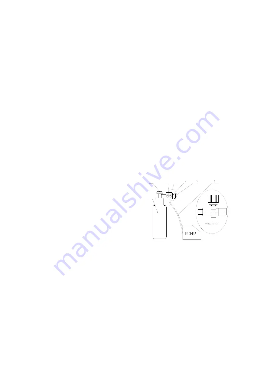
(1) Gas Bottle Valve
(2) Gas Flow Gauge (Set at 20 CFM)
(3) Gas Pressure Gauge
(4) Regulator
(5) Gas Flow Adjuster
(6) Gas Hose
(7) Gas Cylinder
6.5 Open the Gas Bottle Valve on the cylinder of gas.
6.6 Turn the Gas Flow Adjuster on the regulator so that the gas flow rate is set at approximately 20
CFM. Make certain you are reading the correct scale on the gauge.
NOTE:
Slowly open the cylinder valve by turning it counterclockwise until the cylinder pressure
gauge registers on the first gauge of the regulator. Turn the adjustment knob clockwise (right) slowly
to increase gas flow to 20 cfm. To reduce the gas flow turn the adjustment counterclockwise (left).
The gas valve is located on the back panel of the welder and activated by the trigger. Gas flow
should be heard when the trigger is activated. No gas flow will result in a harsh arc with excessive
spatter, a smooth weld bead will be difficult to obtain. Avoid unnecessary gas loss by closing the
tank valve when finished welding.
6.7. Gas selection
Different materials require different shielding gas when MIG welding, refer to the set up chart inside
the wire feed compartment.
7
3
2
1
Содержание MIG 250MGS
Страница 25: ...Page of 28 25 DIAGRAM PARTS LIST...