Manuale/Manual/Manuel/Handbuch/Manual
–
07/2014
Pagina
47
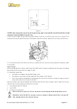
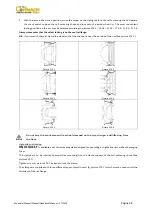
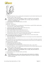
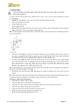
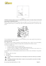
Picture
F13.23
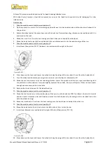
30.
Remove
the
clip.
Remove
the
hook
tool
by
turning
the
spindle
anticlockwise
and
moving
it
towards
the
outside.
31.
Tip
the
tool
carrier
arm
to
its
non
‐
working
position.
32.
Position
the
platform
directly
under
the
wheel
and
lower
the
spindle
until
the
wheel
rests
on
the
platform.
33.
Take
the
mobile
control
unit
to
work
position
B.
34.
When
the
wheel
is
resting
on
the
platform,
check
to
make
sure
the
valve
is
perfectly
centered
with
its
hole.
If
it
is
not,
turn
the
spindle
slightly
to
adjust
the
position.
Fix
the
valve
with
its
locking
ring
and
remove
the
extension.
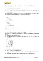
35.
Close
the
arms
of
the
spindle
completely.
Support
the
wheel
to
prevent
it
falling
off.
This
operation
can
be
extremely
dangerous.
Do
it
manually
only
if
you
are
certain
you
can
keep
the
wheel
balanced.
For
large
and
heavy
tyres
an
adequate
lifting
device
must
be
used.
36.
Move
the
platform
to
release
the
wheel
from
the
spindle.
37.
Remove
the
wheel.
13.4
Wheels
with
split
ring
Bead
breaking
and
demounting
Wheels
with
3
–
piece
side
rings
1.
Clamp
the
wheel
on
the
turntable,
as
previously
described
and
ensure
that
is
deflated.
2.
Take
the
mobile
control
unit
to
work
position
C.
3.
Lower
the
tool
holder
arm
into
its
working
position
until
it
hooks
with
ratchet.
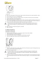
4.
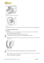
Position
the
bead
breaker
disk
flush
with
the
side
ring
(See
picture
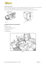
F13.24).
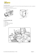
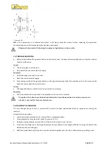
Picture
F13.24
5.
Turn
the
turntable
and
advance
the
bead
breaker
disk
with
small
forward
movements
following
the
side
ring
profile
until
the
first
bead
is
completely
detached.
N.B.:
lubricate
during
this
operation.
For
wheels
with
an
inner
tube,
be
extremely
carefully
when
stopping
the
bead
breaker
disk
from
moving
forward
immediately
after
bead
is
detached
to
prevent
damaging
the
valve
and
the
inner
tube.
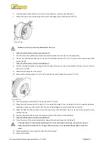
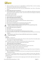
6.
Repeat
the
operation,
making
the
bead
breaker
disk
move
forward
against
the
side
ring
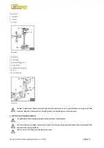
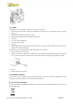
(See
picture
F13.25)
until
the
locking
ring
is
freed,
which
will
be
removed
using
the
side
ring
lever
or
with
the
help
of
the
bead
breaker
disk.
Содержание FT 26S
Страница 2: ......
Страница 6: ......
Страница 33: ...Manuale Manual Manuel Handbuch Manual 07 2014 Pagina 27 19 SCHEMA ELETTRICO...
Страница 34: ...Manuale Manual Manuel Handbuch Manual 07 2014 Pagina 28 20 SCHEMA IDRAULICO...
Страница 35: ...Manuale Manual Manuel Handbuch Manual 07 2014 Pagina 29...
Страница 61: ...Manuale Manual Manuel Handbuch Manual 07 2014 Pagina 55 19 ELECTRICAL DIAGRAM...
Страница 62: ...Manuale Manual Manuel Handbuch Manual 07 2014 Pagina 56 20 HYDRAULIC DIAGRAM...
Страница 63: ...Manuale Manual Manuel Handbuch Manual 07 2014 Pagina 57...
Страница 89: ...Manuale Manual Manuel Handbuch Manual 07 2014 Pagina 83 19 SCHEMA ELECTRIQUE...
Страница 90: ...Manuale Manual Manuel Handbuch Manual 07 2014 Pagina 84 20 SCHEMA HYDRAULIQUE...

