Manuale/Manual/Manuel/Handbuch/Manual
–
07/2014
Pagina
42
2.
Lubricate
both
beads
and
the
rim
with
tyre
manufacturer
recommended
lubricant.
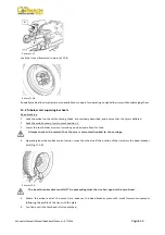
3.
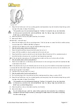
Attach
the
clip
to
the
outside
edge
of
the
rim
at
the
highest
point
(See
picture
F13.14).
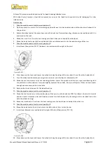
Picture
F13.14
Make
sure
the
clip
is
firmly
attached
to
the
rim.
4.
Take
the
mobile
control
unit
to
work
position
B.
5.
Put
the
tyre
on
the
platform
and
lower
the
spindle
(make
sure
the
clip
is
at
the
high
point).
6.
Lift
the
rim
with
the
tyre
hook
to
it
and
turn
it
anticlockwise
about
15
‐
20
cm.
The
tyre
will
be
positioned
tilted
across
the
rim.
7.
Take
the
mobile
control
unit
to
work
position
C.
8.
Position
the
bead
loosener
disk
against
the
second
of
the
tyre
and
turn
the
spindle
until
the
clip
is
at
the
low
point
(at
6
o’clock).
9.
Move
the
disk
away
from
the
wheel.
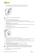
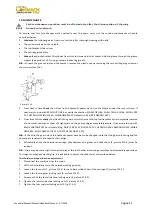
10.
Remove
the
clip
and
replace
it
at
6
o’clock
outside
the
second
bead
(See
picture
F13.15).
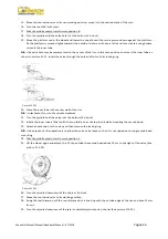
Picture
F13.15
11.
Turn
the
spindle
clockwise
90°
to
bring
the
clip
to
9
o’clock.
12.
Move
the
disk
forward
until
it
is
about
1
‐
2
cm
inside
the
edge
of
the
rim.
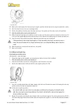
Begin
to
turn
the
spindle
clockwise
checking
to
make
sure
that,
with
a
90°,
the
second
bead
begins
to
slip
into
into
the
center
well.
13.
When
the
bead
is
fully
mounted,
move
the
tool
away
from
the
wheel,
tip
it
to
its
non
‐
working
position
and
remove
the
clip.
14.
Position
under
the
wheel,
lower
the
spindle
until
the
wheel
rests
on
the
platform.
15.
Take
the
mobile
control
unit
to
work
position
B.
16.
Close
the
arms
of
the
spindle
completely.
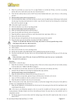
Support
the
wheel
to
prevent
it
falling
off.
This
operation
can
be
extremely
dangerous.
Do
it
manually
only
if
you
are
certain
you
can
keep
the
wheel
balanced.
For
large
and
heavy
tyres
an
adequate
lifting
device
must
be
used.
17.
Move
the
platform
to
remove
the
wheel
from
the
spindle.
18.
Remove
the
wheel.
Содержание FT 26S
Страница 2: ......
Страница 6: ......
Страница 33: ...Manuale Manual Manuel Handbuch Manual 07 2014 Pagina 27 19 SCHEMA ELETTRICO...
Страница 34: ...Manuale Manual Manuel Handbuch Manual 07 2014 Pagina 28 20 SCHEMA IDRAULICO...
Страница 35: ...Manuale Manual Manuel Handbuch Manual 07 2014 Pagina 29...
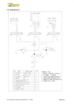
Страница 61: ...Manuale Manual Manuel Handbuch Manual 07 2014 Pagina 55 19 ELECTRICAL DIAGRAM...
Страница 62: ...Manuale Manual Manuel Handbuch Manual 07 2014 Pagina 56 20 HYDRAULIC DIAGRAM...
Страница 63: ...Manuale Manual Manuel Handbuch Manual 07 2014 Pagina 57...
Страница 89: ...Manuale Manual Manuel Handbuch Manual 07 2014 Pagina 83 19 SCHEMA ELECTRIQUE...
Страница 90: ...Manuale Manual Manuel Handbuch Manual 07 2014 Pagina 84 20 SCHEMA HYDRAULIQUE...

