


Lifting of the vehicle
•
T
urn the emergency switch [9] clockwise and check that the power light
[10] is on.
•
Press the up button [11] and lift for about 30 cm, check that the support
points have a correct grip; if correct, continue the climb until the desired
working height is reached.
•
Carefully check the stability of the load throughout the climb.
•
In the event that there is a precarious stability of the vehicle or abnormal
operation of the lift itself, immediately stop the maneuver to climb, wait
for the stabilization of the load and proceed with small descents to the
ground. Reposition the load correctly or proceed to stop the lift if the
cause of the instability turns out to be of a technical nature
Descent of the vehicle
Turn the emergency switch [9] clockwise and check that the power light [10]
is on.
Press the down button [12] and release it once the desired working height
has been reached.
During the entire descent, carefully check the stability of the load.
In the event that a precarious stability of the vehicle or abnormal operation
of the lift is found, immediately stop the maneuver, wait for the stabilization
of the load and proceed with small descents to the ground. Reposition the
load correctly or proceed to stop the lift if the cause of the instability turns out
to be of a technical nature.
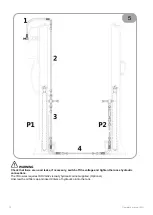
WARNING
The vehicle must only be lifted to the lifting points prescribed by the vehicle manufacturer.
For assistance, contact authorized centers and request the use of original parts.
5.3 EMERGENCY PROCEDURES
These modes are intended for handling emergency situations which may arise due to malfunction, incorrect
loading, power failure, etc.
This maneuver can only be carried out in the presence of the manual pump (
)
The purpose is to enable the operator to retract the runways of the lift in order to allow for removal of the vehicle.
Emergency procedures may be executed by the user, but we recommend contacting our technical service
department to clear up any uncertainties first.
Emergency procedures are potentially hazardous and must be executed with extreme caution: make sure that all
persons are at a safe distance from the lift before proceeding.
Manual Emergency Maneuver
To carry out the descent of the lift when an interruption of the supply of electric current occurs, proceed as follows:
1. Switch off the power supply using the switch on the electrical panel;
2. Remove the protective guards of the mechanical safety devices;
3. Ascent using the hand pump (
) until the mechanical safety devices are released (rotation of the hooking
tooth outwards);
4. Lock the electromagnet in closed position with electric ties;
5. Open the pawl of the YA1 valve by letting the carriages descend gently up to the position on the ground;
6. At the end of this maneuver restore the conditions of use (close the valve YA1, remove the clamps from the
electromagnets, reassemble the casings of the mechanical safety devices, restore the power supply by acting
on the switchboard of the electrical panel
WARNING
Never leave a manual emergency operation on hold as the lift could slowly misalign.
Stop or cancel the manual emergency operation, if necessary.
74
Operator's manual [EN]
Содержание ERCO HC3502 B
Страница 10: ...1 2 VERSIONI E DIMENSIONI DI INGOMBRO 10 Manuale d uso IT ...
Страница 11: ...1 3 DISTRIBUZIONE DEI CARICHI Manuale d uso IT 11 ...
Страница 12: ...1 4 PITTOGRAMMI 12 Manuale d uso IT ...
Страница 13: ...1 5 SCHEMA APPLICAZIONE PITTOGRAMMI 10 5 1 11 Manuale d uso IT 13 ...
Страница 14: ...ZONA OPERATORE 1 6 POSIZIONE OPERATORE 14 Manuale d uso IT ...
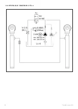
Страница 32: ...8 SCHEMI 8 1 SCHEMA CABLAGGIO COLONNE TYPE 1 32 Manuale d uso IT ...
Страница 33: ...8 1 SCHEMA CABLAGGIO COLONNE TYPE 2 Manuale d uso IT 33 ...
Страница 34: ...8 2 SCHEMA ELETTRICO 400V 3 ph TYPE 1 34 Manuale d uso IT ...
Страница 35: ...8 2 SCHEMA ELETTRICO 400V 3 ph TYPE 2 Manuale d uso IT 35 ...
Страница 36: ...8 3 SCHEMA ELETTRICO 230V 3ph TYPE 1 16A 6 3A 6 3A 36 Manuale d uso IT ...
Страница 37: ...8 3 SCHEMA ELETTRICO 230V 3ph TYPE 2 Manuale d uso IT 37 ...
Страница 38: ...8 4 SCHEMA ELETTRICO 230V 1ph TYPE1 6 3A 6 3A 25A 25A 38 Manuale d uso IT ...
Страница 39: ...8 4 SCHEMA ELETTRICO 230V 1ph TYPE 2 Manuale d uso IT 39 ...
Страница 42: ...8 5 SCHEMA COLLEGAMENTO IDRAULICO 42 Manuale d uso IT ...
Страница 43: ...8 6 SCHEMA IDRAULICO versione 3 5 Ton YA1 24 VAC 230bar Manuale d uso IT 43 ...
Страница 44: ...8 61 SCHEMA IDRAULICO versione 4 5 Ton YA1 24 VAC 295bar 44 Manuale d uso IT ...
Страница 46: ...Note ...
Страница 47: ......
Страница 55: ...1 2 LAYOUT Operator s manual EN 55 ...
Страница 56: ...1 3 LOAD DISTRIBUTION 56 Operator s manual EN ...
Страница 57: ...1 4 PICTOGRAMS Operator s manual EN 57 ...
Страница 58: ...1 4 PICTOGRAMS APPLICATION DIAGRAM 10 5 1 11 58 Operator s manual EN ...
Страница 59: ...OPERATOR AREA 1 5 HAZARDOUS AREAS Operator s manual EN 59 ...
Страница 77: ...8 SCHEMES 8 1 COLUMN WIRING DIAGRAM TYPE 1 Operator s manual EN 77 ...
Страница 78: ...8 1 COLUMN WIRING DIAGRAM TYPE 2 78 Operator s manual EN ...
Страница 79: ...8 2 ELECTRICAL DIAGRAM 400V 3 ph TYPE 1 Operator s manual EN 79 ...
Страница 80: ...8 2 ELECTRICAL DIAGRAM 400V 3 ph TYPE 2 80 Operator s manual EN ...
Страница 81: ...8 3 ELECTRICAL DIAGRAM 230V 3ph TYPE 1 Operator s manual EN 81 ...
Страница 82: ...8 3 ELECTRICAL DIAGRAM 230V 3ph TYPE 2 82 Operator s manual EN ...
Страница 83: ...8 4 ELECTRICAL DIAGRAM 230V 1ph TYPE 1 Operator s manual EN 83 ...
Страница 84: ...8 4 ELECTRICAL DIAGRAM 230V 1ph TYPE 2 84 Operator s manual EN ...
Страница 87: ...8 5 HYDRAULIC CONNECTION DIAGRAM Operator s manual EN 87 ...
Страница 88: ...8 6 HYDRAULIC DIAGRAM 3 5Ton YA1 24 VAC 230bar 88 Operator s manual EN ...
Страница 89: ...8 61 HYDRAULIC DIAGRAM 4 5Ton YA1 24 VAC 295bar Operator s manual EN 89 ...
Страница 91: ...Note ...
Страница 92: ......
Страница 100: ...1 2 VERSIONS ET DIMENSIONS HORS TOUT 100 Manuel d utilisation FR ...
Страница 101: ...1 3 REPARTITION DE CHARGE Manuel d utilisation FR 101 ...
Страница 102: ...1 3 PICTOGRAMMES 102 Manuel d utilisation FR ...
Страница 103: ...1 4 EMPLACEMENT DES PICTOGRAMMES 10 5 1 11 Manuel d utilisation FR 103 ...
Страница 104: ...ZONE DE L OPÉRATEUR 1 5 ZONES A RISQUE 104 Manuel d utilisation FR ...
Страница 122: ...8 DIAGRAMMES 8 1 DIAGRAMME DE CÂBLAGE DE LA COLONNE TYPE 1 122 Manuel d utilisation FR ...
Страница 123: ...8 1 DIAGRAMME DE CÂBLAGE DE LA COLONNE TYPE 2 Manuel d utilisation FR 123 ...
Страница 124: ...8 2 SCHÉMA ÉLECTRIQUE 400V 3 ph TYPE 1 124 Manuel d utilisation FR ...
Страница 125: ...8 2 SCHÉMA ÉLECTRIQUE 400V 3 ph TYPE 2 Manuel d utilisation FR 125 ...
Страница 126: ...8 3 SCHÉMA ÉLECTRIQUE 230V 3 ph TYPE 1 126 Manuel d utilisation FR ...
Страница 127: ...8 3 SCHÉMA ÉLECTRIQUE 230V 3 ph TYPE 2 Manuel d utilisation FR 127 ...
Страница 128: ...8 4 SCHÉMA ÉLECTRIQUE 230V 1 ph TYPE 1 128 Manuel d utilisation FR ...
Страница 129: ...8 4 SCHÉMA ÉLECTRIQUE 230V 1 ph TYPE 1 Manuel d utilisation FR 129 ...
Страница 132: ...8 5 DIAGRAMME DE RACCORDEMENT HYDRAULIQUE 132 Manuel d utilisation FR ...
Страница 133: ...8 6 DIAGRAMME HYDRAULIQUE YA1 24 VAC 230bar Manuel d utilisation FR 133 ...
Страница 134: ...8 6 DIAGRAMME HYDRAULIQUE YA1 24 VAC 290bar 134 Manuel d utilisation FR ...
Страница 136: ...Notes ...
Страница 137: ......
Страница 145: ...1 2 VERSIONEN UND ABMESSUNGEN Betriebsanleitung DE 145 ...
Страница 146: ...1 3 EMPFOHLENE LASTENVERTEILUNG Die Anordnung kann auch umgekehrt erfolgen 146 Betriebsanleitung DE ...
Страница 147: ...1 4 PIKTOGRAMME Betriebsanleitung DE 147 ...
Страница 148: ...1 4 APPLIKATIONSSCHEMA FÜR PIKTOGRAMME 10 5 1 11 148 Betriebsanleitung DE ...
Страница 149: ...STELLUNG DES BEDIENERS 1 5 GEFAHRENBEREICHE Betriebsanleitung DE 149 ...
Страница 168: ...8 SCHEMES 8 1 SPALTENVERDRAHTUNGSDIAGRAMM TYPE 1 168 Betriebsanleitung DE ...
Страница 169: ...8 1 SPALTENVERDRAHTUNGSDIAGRAMM TYPE 2 Betriebsanleitung DE 169 ...
Страница 170: ...8 2 Schaltplan 400V 3 ph TYPE 1 170 Betriebsanleitung DE ...
Страница 171: ...8 2 Schaltplan 400V 3 ph TYPE 2 Betriebsanleitung DE 171 ...
Страница 172: ...8 3 Schaltplan 230V 3 ph TYPE 1 172 Betriebsanleitung DE ...
Страница 173: ...8 3 Schaltplan 230V 3 ph TYPE 2 Betriebsanleitung DE 173 ...
Страница 174: ...8 4 Schaltplan 230V 1 ph TYPE 1 174 Betriebsanleitung DE ...
Страница 175: ...8 4 Schaltplan 230V 1 ph TYPE 2 Betriebsanleitung DE 175 ...
Страница 178: ...8 5 HYDRAULISCHES ANSCHLUSSDIAGRAMM 178 Betriebsanleitung DE ...
Страница 179: ...8 6 HYDRAULISCHES DIAGRAMM 3 5 Ton YA1 24 VAC 230bar Betriebsanleitung DE 179 ...
Страница 180: ...8 6 HYDRAULISCHES DIAGRAMM 4 5 Ton YA1 24 VAC 290bar 180 Betriebsanleitung DE ...
Страница 182: ...Note ...
Страница 183: ......
Страница 191: ...1 2 VERSIONES Y DIMENSIONES TOTALES Manual de uso ES 191 ...
Страница 192: ...1 3 DISTRIBUCIÓN DE CARGAS 192 Manual de uso ES ...
Страница 193: ...1 4 PICTOGRAMAS Manual de uso ES 193 ...
Страница 194: ...1 5 ESQUEMA DE APLICACIÓN DE LOS PICTOGRAMAS 10 5 1 11 194 Manual de uso ES ...
Страница 195: ...POSICIÓN OPERADOR 1 6 ZONAS EN RIESGO Manual de uso ES 195 ...
Страница 213: ...8 ESQUEMAS 8 1 ESQUEMA DE CABLEADO DE COLUMNA TYPE 1 Manual de uso ES 213 ...
Страница 214: ...8 1 ESQUEMA DE CABLEADO DE COLUMNA TYPE 2 214 Manual de uso ES ...
Страница 215: ...8 2 ESQUEMA INSTALACIÓN ELÉCTRICA 400V 3 ph TYPE 1 Manual de uso ES 215 ...
Страница 216: ...8 2 ESQUEMA INSTALACIÓN ELÉCTRICA 400V 3 ph TYPE 2 216 Manual de uso ES ...
Страница 217: ...8 3 ESQUEMA INSTALACIÓN ELÉCTRICA 230V 3ph TYPE 2 Manual de uso ES 217 ...
Страница 218: ...8 3 ESQUEMA INSTALACIÓN ELÉCTRICA 230V 3ph TYPE 2 218 Manual de uso ES ...
Страница 219: ...8 4 ESQUEMA INSTALACIÓN ELÉCTRICA 230V 1ph TYPE 1 Manual de uso ES 219 ...
Страница 220: ...8 4 ESQUEMA INSTALACIÓN ELÉCTRICA 230V 1ph TYPE 2 220 Manual de uso ES ...
Страница 223: ...8 5 ESQUEMA INSTALACIÓN OLEODINÁMICA Manual de uso ES 223 ...
Страница 224: ...8 6 ESQUEMA OLEODINÁMICA3 5 Ton YA1 24 VAC 230bar 224 Manual de uso ES ...
Страница 225: ...8 61 ESQUEMA OLEODINÁMICA 4 5 Ton YA1 24 VAC 290bar Manual de uso ES 225 ...
Страница 227: ...Notes ...


