


5
– INSTRUCTIONS FOR USE
5.1 START UP
W
ARNI
NG
The lift must be put into service by specially trained personnel, in order to assure the correct functioning
of the lift itself and all its mechanical and electrical safety systems.
The instructions to be followed are provided in the final section of this manual, for the use of the technicians who
carry out the start-up procedure only
.
No work on the part of the staff that does not belong to the after-sales service of the manufacturer must be
permitted.
WARNING
The manufacturer declines liability for any damages resulting from failure to follow the above instructions,
which may invalidate the warranty.
5.12 ADJUSTMENT OF THE LIFTING TIME FOR RELEASE OF THE SAFETY LOCKS
The lifting time in the automatic mode needed for the release of the mechanical safety locks is set by the
manufacturer (approximately 3/4 seconds).
In case further adjustment is necessary, work timer KT available on the electrical panel.
5.2 UTILIZATION
The machine must only be used by authorized personnel. Use by personnel who are not familiar with the
procedures specified in this manual could be dangerous.
The operation of the machine is as follows:
Vehicle positioning
When positioning the vehicle over the pads, pay attention to the following recommendations:
a) the total weight of the vehicle must not exceed as indicated on the machine data plate
b) place the vehicle on the pads, making sure that it is aligned and centered with respect to the longitudinal axis of
the lift.
c) the maximum load must be distributed on the four vertices of a rectangle having a transverse dimension of 1000
mm and a longitudinal dimension of 1800 mm. For lower transverse distance values and / or longer longitudinal
distance the lift capacity is reduced. In these cases or in other cases not covered by this manual it is advisable
to contact the manufacturer.
d) the use of accessories not authorized by the manufacturer to modify the support distances of the lifting pads is
forbidden.
e)
The method of lifting the load must not present dangers and must observe the rule that requires stopping after a
short lift to check that the vehicle is correctly positioned and in a safe condition.
The Manufacturer disclaims any and whatever liability for damages to persons, animals or property
arising from non-compliance with the instructions given herewith and/or from an improper use of
the lift or any use other than specified in this manual.
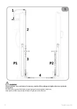
To lift vehicle, proceed as follows:
•
Check that the arms are turned in a way that will not hamper the vehicle access between the lift columns.
•
Turn the arms and pull out the extensions bringing the pads to the points designed for lifting the vehicle as
indicated by the vehicle manufacturer.
WARNING
:
Before lifting a vehicle, always check the load distribution with respect to the vehicle mass, strictly
complying with the LOAD DISTRIBUTION table (Fig. 3). Do not lift the vehicle in case the values found are
not within the limits given in the LOAD DISTRI-BUTION table.
Operator's manual [EN]
73
Содержание ERCO HC3502 B
Страница 10: ...1 2 VERSIONI E DIMENSIONI DI INGOMBRO 10 Manuale d uso IT ...
Страница 11: ...1 3 DISTRIBUZIONE DEI CARICHI Manuale d uso IT 11 ...
Страница 12: ...1 4 PITTOGRAMMI 12 Manuale d uso IT ...
Страница 13: ...1 5 SCHEMA APPLICAZIONE PITTOGRAMMI 10 5 1 11 Manuale d uso IT 13 ...
Страница 14: ...ZONA OPERATORE 1 6 POSIZIONE OPERATORE 14 Manuale d uso IT ...
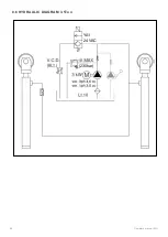
Страница 32: ...8 SCHEMI 8 1 SCHEMA CABLAGGIO COLONNE TYPE 1 32 Manuale d uso IT ...
Страница 33: ...8 1 SCHEMA CABLAGGIO COLONNE TYPE 2 Manuale d uso IT 33 ...
Страница 34: ...8 2 SCHEMA ELETTRICO 400V 3 ph TYPE 1 34 Manuale d uso IT ...
Страница 35: ...8 2 SCHEMA ELETTRICO 400V 3 ph TYPE 2 Manuale d uso IT 35 ...
Страница 36: ...8 3 SCHEMA ELETTRICO 230V 3ph TYPE 1 16A 6 3A 6 3A 36 Manuale d uso IT ...
Страница 37: ...8 3 SCHEMA ELETTRICO 230V 3ph TYPE 2 Manuale d uso IT 37 ...
Страница 38: ...8 4 SCHEMA ELETTRICO 230V 1ph TYPE1 6 3A 6 3A 25A 25A 38 Manuale d uso IT ...
Страница 39: ...8 4 SCHEMA ELETTRICO 230V 1ph TYPE 2 Manuale d uso IT 39 ...
Страница 42: ...8 5 SCHEMA COLLEGAMENTO IDRAULICO 42 Manuale d uso IT ...
Страница 43: ...8 6 SCHEMA IDRAULICO versione 3 5 Ton YA1 24 VAC 230bar Manuale d uso IT 43 ...
Страница 44: ...8 61 SCHEMA IDRAULICO versione 4 5 Ton YA1 24 VAC 295bar 44 Manuale d uso IT ...
Страница 46: ...Note ...
Страница 47: ......
Страница 55: ...1 2 LAYOUT Operator s manual EN 55 ...
Страница 56: ...1 3 LOAD DISTRIBUTION 56 Operator s manual EN ...
Страница 57: ...1 4 PICTOGRAMS Operator s manual EN 57 ...
Страница 58: ...1 4 PICTOGRAMS APPLICATION DIAGRAM 10 5 1 11 58 Operator s manual EN ...
Страница 59: ...OPERATOR AREA 1 5 HAZARDOUS AREAS Operator s manual EN 59 ...
Страница 77: ...8 SCHEMES 8 1 COLUMN WIRING DIAGRAM TYPE 1 Operator s manual EN 77 ...
Страница 78: ...8 1 COLUMN WIRING DIAGRAM TYPE 2 78 Operator s manual EN ...
Страница 79: ...8 2 ELECTRICAL DIAGRAM 400V 3 ph TYPE 1 Operator s manual EN 79 ...
Страница 80: ...8 2 ELECTRICAL DIAGRAM 400V 3 ph TYPE 2 80 Operator s manual EN ...
Страница 81: ...8 3 ELECTRICAL DIAGRAM 230V 3ph TYPE 1 Operator s manual EN 81 ...
Страница 82: ...8 3 ELECTRICAL DIAGRAM 230V 3ph TYPE 2 82 Operator s manual EN ...
Страница 83: ...8 4 ELECTRICAL DIAGRAM 230V 1ph TYPE 1 Operator s manual EN 83 ...
Страница 84: ...8 4 ELECTRICAL DIAGRAM 230V 1ph TYPE 2 84 Operator s manual EN ...
Страница 87: ...8 5 HYDRAULIC CONNECTION DIAGRAM Operator s manual EN 87 ...
Страница 88: ...8 6 HYDRAULIC DIAGRAM 3 5Ton YA1 24 VAC 230bar 88 Operator s manual EN ...
Страница 89: ...8 61 HYDRAULIC DIAGRAM 4 5Ton YA1 24 VAC 295bar Operator s manual EN 89 ...
Страница 91: ...Note ...
Страница 92: ......
Страница 100: ...1 2 VERSIONS ET DIMENSIONS HORS TOUT 100 Manuel d utilisation FR ...
Страница 101: ...1 3 REPARTITION DE CHARGE Manuel d utilisation FR 101 ...
Страница 102: ...1 3 PICTOGRAMMES 102 Manuel d utilisation FR ...
Страница 103: ...1 4 EMPLACEMENT DES PICTOGRAMMES 10 5 1 11 Manuel d utilisation FR 103 ...
Страница 104: ...ZONE DE L OPÉRATEUR 1 5 ZONES A RISQUE 104 Manuel d utilisation FR ...
Страница 122: ...8 DIAGRAMMES 8 1 DIAGRAMME DE CÂBLAGE DE LA COLONNE TYPE 1 122 Manuel d utilisation FR ...
Страница 123: ...8 1 DIAGRAMME DE CÂBLAGE DE LA COLONNE TYPE 2 Manuel d utilisation FR 123 ...
Страница 124: ...8 2 SCHÉMA ÉLECTRIQUE 400V 3 ph TYPE 1 124 Manuel d utilisation FR ...
Страница 125: ...8 2 SCHÉMA ÉLECTRIQUE 400V 3 ph TYPE 2 Manuel d utilisation FR 125 ...
Страница 126: ...8 3 SCHÉMA ÉLECTRIQUE 230V 3 ph TYPE 1 126 Manuel d utilisation FR ...
Страница 127: ...8 3 SCHÉMA ÉLECTRIQUE 230V 3 ph TYPE 2 Manuel d utilisation FR 127 ...
Страница 128: ...8 4 SCHÉMA ÉLECTRIQUE 230V 1 ph TYPE 1 128 Manuel d utilisation FR ...
Страница 129: ...8 4 SCHÉMA ÉLECTRIQUE 230V 1 ph TYPE 1 Manuel d utilisation FR 129 ...
Страница 132: ...8 5 DIAGRAMME DE RACCORDEMENT HYDRAULIQUE 132 Manuel d utilisation FR ...
Страница 133: ...8 6 DIAGRAMME HYDRAULIQUE YA1 24 VAC 230bar Manuel d utilisation FR 133 ...
Страница 134: ...8 6 DIAGRAMME HYDRAULIQUE YA1 24 VAC 290bar 134 Manuel d utilisation FR ...
Страница 136: ...Notes ...
Страница 137: ......
Страница 145: ...1 2 VERSIONEN UND ABMESSUNGEN Betriebsanleitung DE 145 ...
Страница 146: ...1 3 EMPFOHLENE LASTENVERTEILUNG Die Anordnung kann auch umgekehrt erfolgen 146 Betriebsanleitung DE ...
Страница 147: ...1 4 PIKTOGRAMME Betriebsanleitung DE 147 ...
Страница 148: ...1 4 APPLIKATIONSSCHEMA FÜR PIKTOGRAMME 10 5 1 11 148 Betriebsanleitung DE ...
Страница 149: ...STELLUNG DES BEDIENERS 1 5 GEFAHRENBEREICHE Betriebsanleitung DE 149 ...
Страница 168: ...8 SCHEMES 8 1 SPALTENVERDRAHTUNGSDIAGRAMM TYPE 1 168 Betriebsanleitung DE ...
Страница 169: ...8 1 SPALTENVERDRAHTUNGSDIAGRAMM TYPE 2 Betriebsanleitung DE 169 ...
Страница 170: ...8 2 Schaltplan 400V 3 ph TYPE 1 170 Betriebsanleitung DE ...
Страница 171: ...8 2 Schaltplan 400V 3 ph TYPE 2 Betriebsanleitung DE 171 ...
Страница 172: ...8 3 Schaltplan 230V 3 ph TYPE 1 172 Betriebsanleitung DE ...
Страница 173: ...8 3 Schaltplan 230V 3 ph TYPE 2 Betriebsanleitung DE 173 ...
Страница 174: ...8 4 Schaltplan 230V 1 ph TYPE 1 174 Betriebsanleitung DE ...
Страница 175: ...8 4 Schaltplan 230V 1 ph TYPE 2 Betriebsanleitung DE 175 ...
Страница 178: ...8 5 HYDRAULISCHES ANSCHLUSSDIAGRAMM 178 Betriebsanleitung DE ...
Страница 179: ...8 6 HYDRAULISCHES DIAGRAMM 3 5 Ton YA1 24 VAC 230bar Betriebsanleitung DE 179 ...
Страница 180: ...8 6 HYDRAULISCHES DIAGRAMM 4 5 Ton YA1 24 VAC 290bar 180 Betriebsanleitung DE ...
Страница 182: ...Note ...
Страница 183: ......
Страница 191: ...1 2 VERSIONES Y DIMENSIONES TOTALES Manual de uso ES 191 ...
Страница 192: ...1 3 DISTRIBUCIÓN DE CARGAS 192 Manual de uso ES ...
Страница 193: ...1 4 PICTOGRAMAS Manual de uso ES 193 ...
Страница 194: ...1 5 ESQUEMA DE APLICACIÓN DE LOS PICTOGRAMAS 10 5 1 11 194 Manual de uso ES ...
Страница 195: ...POSICIÓN OPERADOR 1 6 ZONAS EN RIESGO Manual de uso ES 195 ...
Страница 213: ...8 ESQUEMAS 8 1 ESQUEMA DE CABLEADO DE COLUMNA TYPE 1 Manual de uso ES 213 ...
Страница 214: ...8 1 ESQUEMA DE CABLEADO DE COLUMNA TYPE 2 214 Manual de uso ES ...
Страница 215: ...8 2 ESQUEMA INSTALACIÓN ELÉCTRICA 400V 3 ph TYPE 1 Manual de uso ES 215 ...
Страница 216: ...8 2 ESQUEMA INSTALACIÓN ELÉCTRICA 400V 3 ph TYPE 2 216 Manual de uso ES ...
Страница 217: ...8 3 ESQUEMA INSTALACIÓN ELÉCTRICA 230V 3ph TYPE 2 Manual de uso ES 217 ...
Страница 218: ...8 3 ESQUEMA INSTALACIÓN ELÉCTRICA 230V 3ph TYPE 2 218 Manual de uso ES ...
Страница 219: ...8 4 ESQUEMA INSTALACIÓN ELÉCTRICA 230V 1ph TYPE 1 Manual de uso ES 219 ...
Страница 220: ...8 4 ESQUEMA INSTALACIÓN ELÉCTRICA 230V 1ph TYPE 2 220 Manual de uso ES ...
Страница 223: ...8 5 ESQUEMA INSTALACIÓN OLEODINÁMICA Manual de uso ES 223 ...
Страница 224: ...8 6 ESQUEMA OLEODINÁMICA3 5 Ton YA1 24 VAC 230bar 224 Manual de uso ES ...
Страница 225: ...8 61 ESQUEMA OLEODINÁMICA 4 5 Ton YA1 24 VAC 290bar Manual de uso ES 225 ...
Страница 227: ...Notes ...


