21
www.powerbox-systems.com
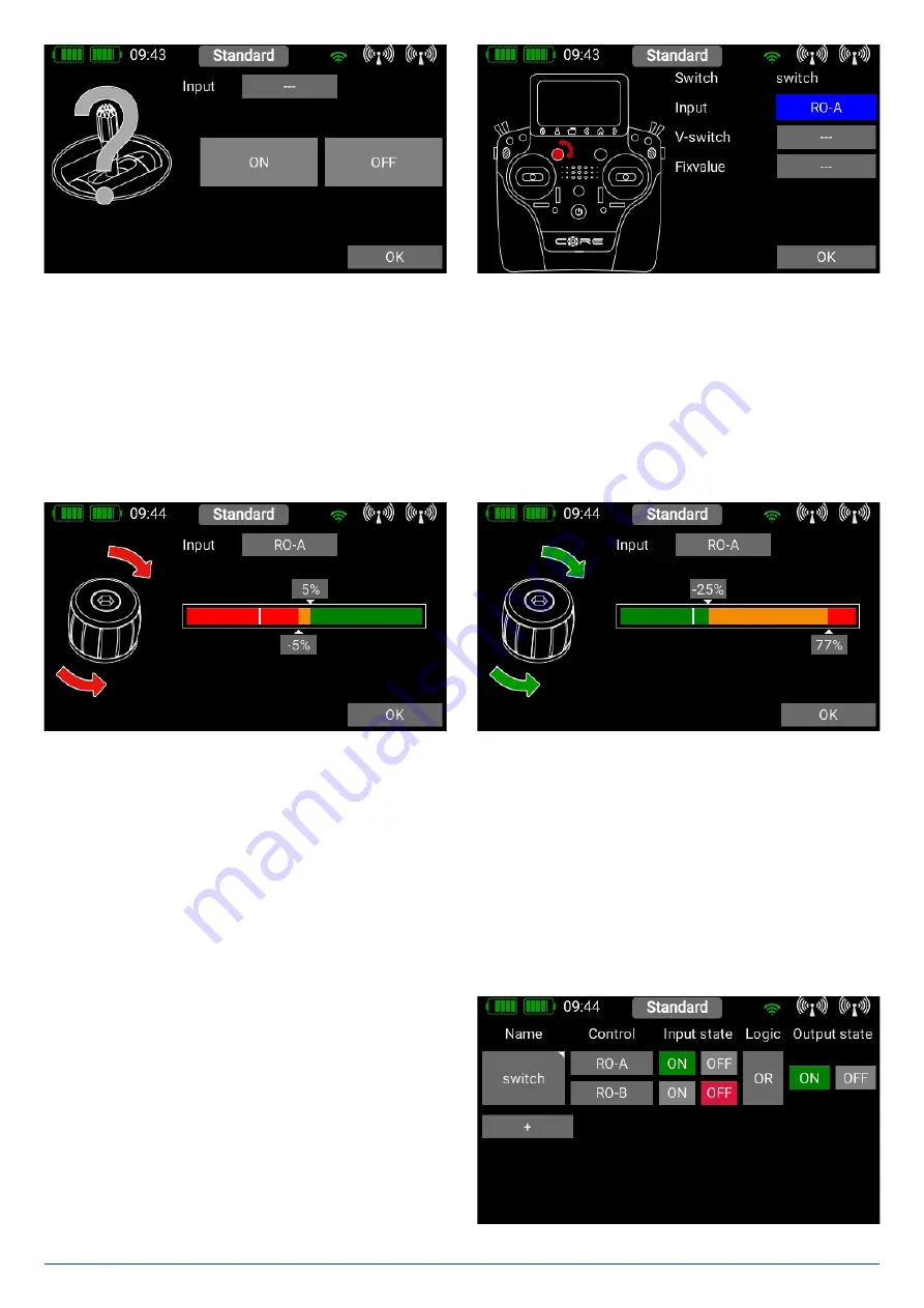
A further alternative is to define a fixed value -
On
or
Off
. This is necessary, for example, if you only wish to assign a switching
threshold to one linear control. In this case select one transmitter control as fixed value, and define a linear control for the other
transmitter control.
Yet another option is to use the output of a previously defined logical switch in turn as a transmitter control input.
In this way you can set up a logical link between three or more switches!
In this example a linear rotary control has been selected. In the following section you will see your transmitter control on the left,
and a bar display on the right showing two switching points.
The two switching points can now be placed in any position you like by moving them with your finger. The red area indicates
the “
Off
” state; the green area the “
On
” state. The orange area indicates “
hysteresis
”, i.e. the area in which no switching takes
place.
You can very easily reverse the “
Off
” state and the “On state” by moving one of the two switching point sliders in front of or
behind the other. This adaptability provides maximum flexibility and simplicity, and you can immediately check the effect of your
settings by moving the switch or linear control. The transmitter control symbol on the left changes color to indicate the switched
state.
If you wish to use a switch, you can very easily set the desired switch position to
ON
. If you select a 3-position switch it is also
possible to set two
ON
positions. Press
OK
once you have completed your settings.
You are now returned to the virtual switch overview, and you
can define the second input using exactly the same procedure
as the first.
Selecting
AND
or
OR
logic defines the switching characte-
ristics you wish to use. At far right under
Output
you will see
the result of the two inputs. The virtual switch is immediately
available in order to control
Functions
, or switch a
Mixer
or a
Servo Cut-Off
.


