Continental Hydraulics Installation Manual
Page 13 of 33
CEM-AA-B
CHI 1020611 01/2016
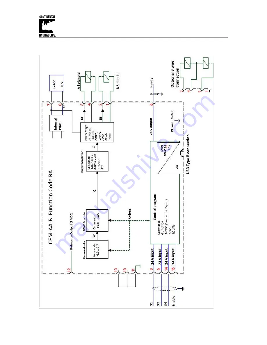
Circuit Diagram Function RA
Страница 1: ...Control Valves Function mode RA This mode accepts 3 independent switch inputs each which has independently adjustable speed and ramp controls Inputs are additive for up to 8 unique preset speed and r...
Страница 2: ...ction AA 9 Circuit Diagram Function A B 10 Terminal Identification A B Function 11 Parameter List Function A B 12 Circuit Diagram Function RA 13 Terminal Identification RA Function 14 Parameter List F...
Страница 3: ...inal PWM output current mA 500 2600 broken wire monitored and short circuit proof PWM frequency Hz 61 2604 adjustable in steps Sample time process control ms 1 Sample time solenoid current control ms...
Страница 4: ...are inconsistent To acknowledge the error the data has to be saved with the SAVE command or the corresponding Function button in the CHI PC program If one of the FUNCTION parameter is changed to an i...
Страница 5: ...0 v3 5 0 zip 4 Connect to Laptop via USB to USB Type B communication cable 5 Open the Options Tab and in setting verify that the correct com port full Duplex and 57 6K Baud rates are selected 6 Select...
Страница 6: ...ltage rating to power supply typically 12 or 24 volts A 3 amp medium action fuse is recommended in the power supply line Wiring to Valve Two conductors are required for each solenoid There is no need...
Страница 7: ...Continental Hydraulics Installation Manual Page 7 of 33 CEM AA B CHI 1020611 01 2016 Circuit Diagram Function AA...
Страница 8: ...nd input signal W range 100 100 corresponds with 10 10 V or 4 20 mA 0 V reference for the signal inputs Attention PIN 8 and PIN 11 are connected internally Connection Digital inputs and outputs Enable...
Страница 9: ...nput scaling via linear equation X 22 AA 1 100 Ramptime acceleration A in ms X X 22 AA 2 100 Ramptime deceleration A in ms X X 22 AA 3 100 Ramptime acceleration B in ms X X 22 AA 4 100 Ramptime decele...
Страница 10: ...Continental Hydraulics Installation Manual Page 10 of 33 CEM AA B CHI 1020611 01 2016 Circuit Diagram Function A B...
Страница 11: ...0 mA PIN 13 14 Command input signal B range 0 100 corresponds with 0 10 V or 4 20 mA 0 V reference for the signal inputs Attention PIN 8 and PIN 11 are connected internally Connection Digital inputs a...
Страница 12: ...deceleration A in ms X X 22 AB UP 100 Ramptime acceleration B in ms X X 22 AB DOWN 100 Ramptime deceleration B in ms X X 25 CCA characteristic curve Free definable characteristic linearization X 25 C...
Страница 13: ...Continental Hydraulics Installation Manual Page 13 of 33 CEM AA B CHI 1020611 01 2016 Circuit Diagram Function RA...
Страница 14: ...solenoid B Connection Analogue input signals Digital gate inputs for selecting the command value PIN 6 S1 PIN 9 S2 PIN 14 S4 The whole range of set points can be chosen by binary coding of these input...
Страница 15: ...related to the digital inputs in ms X X 24 RA 2 100 Ramptime related to the digital inputs in ms X X 24 RA 3 100 Ramptime related to the digital inputs in ms X X 24 RA 4 100 Ramptime related to the d...
Страница 16: ...meter the ID button has to be pressed in order to rebuild the parameter table and a SAVE button has to be conducted LG Changing the language for the help texts Command Parameters Unit Group LG X x EN...
Страница 17: ...itoring functions are always active because otherwise no errors are detectable via the READY output Deactivating is possible especially for troubleshooting AUTO MODE The module checks each second the...
Страница 18: ...nput S1 PIN 6 is off this parameter scales the output current The default setting is 10000 100 which does not change the output If USCALE is set to 10000 the polarity of the output will be flipped by...
Страница 19: ...output current and the READY output if the input signal leaves the permitted range after scaling This function makes it possible to detect a short circuit or cable break of a joystick or potentiomete...
Страница 20: ...ut signal 0 100 nominal output current 100 0 Directional valves This command allows a switch over of the output polarity AINA Current Voltage input AINB Current Voltage input Command Parameters Unit G...
Страница 21: ...ings to be used Typical settings examples FUNCTION AA A B C Input signal Description AIN I 20 20 0 V OR AIN I 1000 1000 0 V 10 10 V Voltages input Usable 10 10V 20V for a working range of 100 100 two...
Страница 22: ...d to 100 signal step AA Ramp function Command Parameters Unit Group FUNCTION AA I X i 1 4 x 1 120000 ms STD AA RA 4Q Mode Four quadrants ramp function The first quadrant means the acceleration ramp fo...
Страница 23: ...for each command value and a four quadrant ramp function 4Q with set point independent ramp times for acceleration and deceleration in both directions S 0 S 7 Presetting command values Command Paramet...
Страница 24: ...x 1 120000 ms STD RA SD Mode Presetting of the ramp times Functionality depends on command RMODE RMODE SD In this mode every command value has its own ramp time For example if you choose set point S 1...
Страница 25: ...on For activating the parameter CCMODE has to be switched to ON In case of using single solenoid valves only the first quadrant is active The curve is calculated according to the equation of the linea...
Страница 26: ...has to be switched to ON The positive indexes stand for the solenoid A the negative ones represent the solenoid B The curve is calculated according to the equation of the linear interpolation y x x1...
Страница 27: ...X value the output signal the maximum valve current will be defined With the MIN value the overlap dead band of the valve will be compensated Via the TRIGGER command the activation point of the MIN fu...
Страница 28: ...al the maximum valve current is defined by the MAX I value The overlap dead band of the valve is compensated by the MIN I value The activation of the MIN function is set with the TRIGGER No output can...
Страница 29: ...ly with this command Different amplitudes or frequencies may be required depending on the respective valve The dither amplitude is defined in of the nominal current see CURRENT command CAUTION The PPW...
Страница 30: ...Hz 1562 Hz 1736 Hz 1953 Hz 2232 Hz and 2604 Hz The optimum frequency depends on the valve Attention The PPWM and IPWM parameters should be adapted when using low PWM frequencies because of the longer...
Страница 31: ...The PI current controller for the solenoids is parameterized with these commands CAUTION These parameters should not be changed without adequate measurement facilities and experiences Attention if the...
Страница 32: ...l A Command value after linearization channel A Command value to current controller channel A Command value after input scaling channel B Command value after linearization channel B Command value to c...
Страница 33: ...ne with the assistance of the valve data sheets The RC mode in monitor can be used to analyze faults FAULT CAUSE SOLUTION ENABLE is active the module does not respond and the READY LED is off Probably...