2. Setup
CNT24-4(PCI)H
21
Step 5 Checking Operations with the Diagnosis
Program
Use the diagnosis program to check that the board and driver software work normally, thereby you can
confirm that they have been set up correctly.
What is the Diagnosis Program?
The diagnosis program diagnoses the states of the board and driver software.
It can also be used as a simple checker when an external device is actually connected.
Using the “Diagnosis Report” feature reports the driver settings, the presence or absence of the board,
I/O status, and interrupt status.
Check Method
The diagnosis program tests the board actually connected to an external device to check whether count
values are displayed correctly and whether signals are successfully turned on/off. See the following
section about how they are connected.
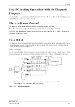
Connection diagram
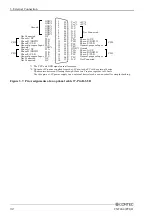
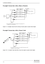
Use the following connection to connect the rotary encoder to the photo coupler isolated input. For the
details on the example connection of input and signal position, see Chapter 3 "External Connection".
* If you apply a 12V external power supply for this test, the resister R should be about 400
Ω
.
. However in case of 5V power supply, the R is not required.
(Pin No. of Connector)
CH0 : 8 CH2 : 27
CH1 : 18 CH3 : 37
CNT24-4(PCI)H
CN1
Power supply
0V
Shield
Encoder
CH0 : 9 CH2 : 28
CH1 : 14 CH3 : 33
CH0 : 10 CH2 : 29
CH1 : 15 CH3 : 34
CH0 : 11 CH2 : 30
CH1 : 16 CH3 : 35
Phase-A
Plus Common
R
R
R
Phase-B
Phase-Z
Phase-A
Phase-B
Phase-Z
Figure 2.3. Connection diagram
Содержание CNT24-4(PCI)H
Страница 1: ...PC HELPER 4ch 24Bit Up Down Counter Board for PCI CNT24 4 PCI H User s Guide CONTEC CO LTD ...
Страница 7: ...vi CNT24 4 PCI H ...
Страница 15: ...1 Before Using the Product 8 CNT24 4 PCI H ...
Страница 31: ...2 Setup 24 CNT24 4 PCI H 3 Click on the End button to finish condition setting Click on the End Button ...
Страница 35: ...2 Setup 28 CNT24 4 PCI H ...
Страница 53: ...4 Function 46 CNT24 4 PCI H ...


