


2. Setup
14
CNT24-4(PCI)H
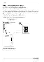
Step 2 Setting the Hardware
This section describes how to set the board and plug it on your PC.
The board may have some switches and jumpers that need to be preset.
Check the on-board switches and jumpers before plugging the board into an expansion slot.
The board can be set up even with the factory defaults untouched. You can change board settings later.
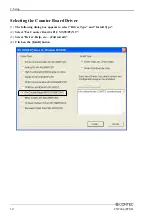
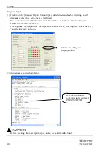
Parts of the Board and Factory Defaults
Figure 2.1. shows the names of major parts on the board.
Note that the switch setting shown below is the factory default.
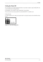
SW1
BOARD ID
CN2
- BOARD ID
Setting Switch
01
23
4
5
67
9A
B
C
D
EF
8
CN1
CNT24-4(PCI)H
SW1
BOARD ID
- Interface connector
for TTL level input (CN2)
- Interface connector
for opto-coupler
resistance input
(CN1)
Figure 2.1. Component Locations
Содержание CNT24-4(PCI)H
Страница 1: ...PC HELPER 4ch 24Bit Up Down Counter Board for PCI CNT24 4 PCI H User s Guide CONTEC CO LTD ...
Страница 7: ...vi CNT24 4 PCI H ...
Страница 15: ...1 Before Using the Product 8 CNT24 4 PCI H ...
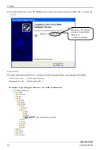
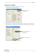
Страница 31: ...2 Setup 24 CNT24 4 PCI H 3 Click on the End button to finish condition setting Click on the End Button ...
Страница 35: ...2 Setup 28 CNT24 4 PCI H ...
Страница 53: ...4 Function 46 CNT24 4 PCI H ...


