Setup
BUF-PCI(PC), BUF-PCI(98)
10
Setting Up and Mounting
the BUS-PCI(PC) or BUS-PCI(98) Board
Setting Up I/O Expansion Unit Power Control
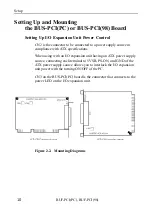
CN2 is the connector to be connected to a power supply source in
compliance with ATX specifications.
When using with an I/O expansion unit having an ATX power supply
source, connecting each terminal to 5VSB, PS-ON, and GND of the
ATX power supply source allows you to interlock the I/O expansion
unit power with the turning ON/OFF of the PC.
CN3 on the BUS-PCI(PC) board is the connector that connects to the
power LED on the I/O expansion unit.
Figure 2.2. Mounting Diagrams
Содержание BUF-PCI(98)
Страница 2: ...BUF PCI PC BUF PCI 98 Bus Expansion User s Guide ...
Страница 92: ...Programming BUF PCI PC BUF PCI 98 84 ...
Страница 98: ...System Reference BUF PCI PC BUF PCI 98 90 ...
Страница 102: ...Troubleshooting BUF PCI PC BUF PCI 98 94 ...
Страница 105: ...A 41 901 LZF6231 021010 980713 ...


