2-1
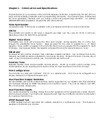
Chapter 2 - System Configuration
Repeater and Transceiver
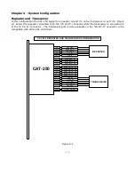
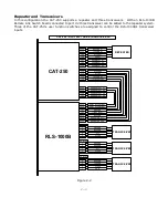
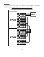
In this configuration the CAT-250 supports a repeater on port #1 and a transceiver on port #2. Figure
2-1 shows the repeater connected to J2 the “25 Pin D” connector while the transceiver is connected to
J1 the “9 Pin D” connector. The transceiver port is also available on the “25 Pin D” connector to be
compatible with other CAT controllers.
CAT-250
CAT-250 REPEATER AND TRANSCEIVER CONFIGURATION
J2-6
J2-4
J2-25
J2-10
J2-11
J2-13
J2-1
COR #1
CTCSS #1
PTT #1
TX AUDIO #1
RX AUDIO #1
GROUND
USER INPUT #3
USER INPUT #4
USER INPUT #1
USER INPUT #2
J2-22
J2-21
J2-2
J2-15
J2-14
USER OUTPUT #3
USER OUTPUT #2
USER OUTPUT #1
J2-19
J2-20
USER OUTPUT #4
J2-17
J2-16
GROUND
+12VDC OUTPUT
J1-1
J1-4
J1-3
J1-2
COR #2
TX AUDIO #2
PTT #2
CTCSS #2
RX AUDIO #2
J1-5
J2-8
USER OUTPUT #6
GROUND
J1-8
REPEATER
TRANSCEIVER
J2-7
USER OUTPUT #5
Figure 2-1
Содержание CAT-250
Страница 49: ...9 1 Chapter 9 Drawings CAT 250 Repeater Controller Figure 9 1 ...
Страница 51: ...10 2 ...
Страница 52: ...10 3 ...
Страница 53: ...10 1 ...


