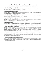
3-9
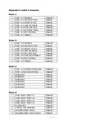
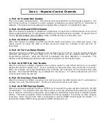
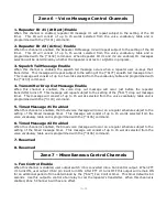
1. Repeater ID #1 (At Rest) Enable
When this channel is enabled, repeater ID message #1 will repeat subject to the setting of the ID
timer. This ID will consist of up to 15 words selected from the voice vocabulary table and is
programmed with the [*3101] command.
2. Repeater ID #2 (Active) Enable
When this channel is enabled, the Repeater ID Message #2 will repeat subject to the setting of the ID
timer. This ID will consist of up to 15 words selected from the voice vocabulary table and is
programmed with the [*3102] command. When Repeater ID #1 and #2 are enabled, ID messages
selection will be determined by whether the repeater is at rest or a QSO is in progress.
3. Squelch Tail Message Enable
When this channel is enabled, the squelch tail message occurs when a repeater user un-keys their
transmitter. This message will repeat subject to the setting of the [*610*] squelch tail message timer.
This message will consist of up to 15 words selected from the vocabulary table and programmed with
the [*3103] command.
4. Transmitter Drop Out Message Enable
When this channel is enabled, the voice drop out message will occur just before the repeater
transmitter turns off. This message will repeat subject to the setting of the [*611*] drop out message
timer. This message will consist of up to 15 words selected from the voice vocabulary table and is
programmed with the [*3104] command.
5. Timed Message #1 Enabled
When this channel is enabled, the timed voice message will occur on a regular schedule subject to the
setting of the timed message timer. This message will consist of up to 15 words selected from the
voice vocabulary table and is programmed with the [*3105] command.
6. Timed Message #2 Enabled
When this channel is enabled, the timed voice message will occur on a regular schedule subject to the
setting of the timed message timer. This message will consist of up to 15 words selected from the
voice vocabulary table and is programmed with the [*3106] command.
7. Reserved
8. Reserved
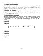
1. Fan Control Enable
When this channel is enabled, user output switch #6 is converted into a Fan Control output. When PTT
#1 turns ON, user output #6 J2 pin 8 will turn ON. After PTT #1 turns OFF this output will remain ON
for an additional period of time determined by the [*612*] Fan Control timer. This timer default is 60
seconds. Use this output to control a fan relay to cool the repeater’s transmitter. When this channel is
enabled, Zone 5 Channel 6 will have no effect.
Zone 6 – Voice Message Control Channels
Zone 7 - Miscellaneous Control Channels
Содержание CAT-250
Страница 49: ...9 1 Chapter 9 Drawings CAT 250 Repeater Controller Figure 9 1 ...
Страница 51: ...10 2 ...
Страница 52: ...10 3 ...
Страница 53: ...10 1 ...

