


4–18
SAN Switch Integrated/32 and Integrated/64 Installation and Hardware Guide
4–18
SAN Switch Integrated/32 and Integrated/64 Installation and Hardware Guide
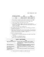
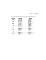
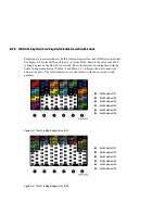
Following are representations of the ISL cabling diagrams for the SAN Integrated Switch.
See Figure 4–5 for the IS/32 and Figure 4–6 for the IS/64. Refer to the color-coded ISL
cabling diagram on the front of your switch. The color diagram, in conjunction with the
Cable Configuration matrix (Table 4–2 and Table 4–3), indicates the interconnectivity
between the ports. The cables themselves are also labeled with their port and switch
numbers.
Figure 4–5: The ISL cabling diagram for an IS/32
Figure 4–6: The ISL cabling diagram for an IS/64
1
Switch element #1
2
Switch element #2
3
Switch element #3
4
Switch element #4
5
Switch element #5
6
Switch element #6
1
Switch element #1
2
Switch element #2
3
Switch element #3
4
Switch element #4
5
Switch element #5
6
Switch element #6