


Installing the SAN Integrated Switch
2–9
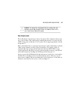
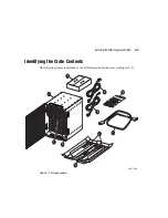
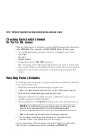
Figure 2–4: Installing the SAN Integrated Switch in the rack
NOTE:
The rail is divided into units, each unit is marked with a small round hole and has three
square openings for mounting equipment. The rail is positioned such that the top front screw is
installed above the small round hole and the second screw below the round hole.
1
Air flow
2
Rails in Rack
3
Left and Right Rack Mount Brackets
4
Left and Right Upper Rear Brackets (straight section)
5
Left and Right Upper Rear Brackets (L section)
6
Cage nuts
1
4
4
3
3
5
5
6
2
SHR-2200A